This thread has been locked.

If you have a related question, please click the "Ask a related question" button in the top right corner. The newly created question will be automatically linked to this question.

MCT8316AEVM: How to setup the evaluation board so that I can interface with MCT8316A directly

Part Number: MCT8316AEVM
Other Parts Discussed in Thread: MCT8316A, , MCT8316ZTEVM, MCT8316Z

Tool/software:

Hi,

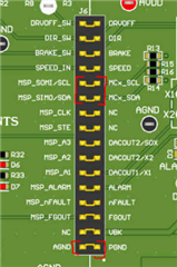
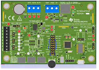
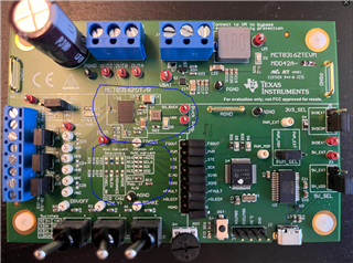
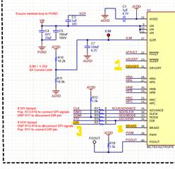
I am using an Non-TI MCU to interface with the MCT8316A driver on the MCT8316AEVM board. Can you please advise me how to setup all the pins on J6 such that I can bypass the MSR430 and interface with MCT8316A directly? 

thank you!

Ryan

  • Hi Ryan,

    Thanks for the e2e. You can remove all the jumpers on J6 and connect your MCU directly to J6's I2C pins (marked below). Make sure your MCU's I2C lines are connected to the right side of the marked jumpers.

    Let me know if there's any issues with this, I have not tried this before.

    Regards,
    Sachin S

  • Thank you! I am working on t his part. BTY, does this method apply to MCT8316ZTEVM board? or is there any other way to work around?

  • also, do you have any instruction pages about setting up I2C for MCT8316A and setting up SPI for MCT8316Z? does this page (https://e2e.ti.com/support/motor-drivers-group/motor-drivers/f/motor-drivers-forum/937258/faq-spi-configuration-and-use) apply to the SPI configuration of MCT8316Z? thank you!

  • Hi Sichuan,

    It should work, in my opinion. Using these pins in a similar way as I have mentioned before. But again, I have not tried this, let me know if you face any issues.

    Also the e2e faq you mentioned does not apply to the MCT8316Z as the SPI format is slightly different (image below). But you can easily modify the code from the faq to update to the new format.

    Please refer to this Application Note for information on I2C implementation.


    Regards,
    Sachin S

  • Thanks for the update. I am working on both boards now. one more question regarding the MCT8316ZTEVM. I saw these instruction about using SPI from the MCT8316ZTEVM_User guide (check image below). Because I don't see any bridge jumpers on these silk screen boxes of the evaluation board, Do I still need to follow these instruction to use the SPI? OR I just need to use J6 to deploy the SPI communication without worrying about the silk screen boxes.
     

  • BTW, are there any pullup requirements on the STE, mosi, miso and sclk pin if I want to deploy SPI communication with external MCU? I am asking because I always get 255 from MISO pin, regardless read or write operation I command.  Besides, in the datasheet of MCT8316Z, for SPI, "the nSCS should be pulled high for at least 400 ns between words". Does this mean: if two 16-bit word(1bit W/R + 6 bit addr + 1 bit parity + 8 bit data) are to be transmitted, the nSCS should be pulled high  for 400ns after completion of transmission of the first word, and then continue to the transmission of the second word?


  • Hi Sichuan,

    Yes you are right in assuming this.

    the nSCS should be pulled high  for 400ns after completion of transmission of the first word, and then continue to the transmission of the second word?

    By default, the SDO pin is operated in Open drain mode, which can be configured in the SDO_MODE bit. So you will need a pull up on SDO.

    Regards,

    Sachin S

  • Thanks Sachin. BTW, do I need to populate R13 ~ R16 and DNP R17 (see the following picture)? it seems that the evaluation board I got is by default a Hardware variant of MCT8316ZT. I am not sure if I need to change the hardware settings in order to use the SPI interface of the MCT8316Z. I am asking because I found that when I only use J6 pin to SPI interface with the driver chip, the DRVOFF and BRAKE switches still functional but the DIR switch does not work. I am guessing that may be due to the hardware settings. Also. The driver chip we are targeting is MCT8316Z0R. So I wonder whether this hardware setting change is a must-have, such that we can leverage this evaluation board to evaluate the performance of MCT8316Z0R. We still want to use an external MCU to communicate with the driver chip on the MCT8316ZTEVM. 

  • Hi Sichuan,

    You are right, you need to populate these according to the recommendation from the user's guide for the device to work. If you look at the design, the highlighted signals are tied to the device on through the resistors R13 to R16. And these highlighted signals are also the signals which exist on J6 for you to connect to MCU. 

    the DRVOFF and BRAKE switches still functional but the DIR switch does not work

    This is not expected though. Could you give more details on this?

    Regards,
    Sachin S

  • The setup was: (1) R13~ R16 were not populated, and R17 was populated; (2) All the bridge connections between MSP430 and MCT8316Z on J6 were unpolulated. (2) The STE, MOSI, MISO, SCLK pins on J6 were connected to a SPI module of an external MCU,  nSLEEP, AGND and PWM pins of J6 were connected to an external MCU; (3) these pins were configured correctly on the external MCU (my guess)

    Results:

    (1) the BLDC motor can be driven by MCT8316Z with the PWM input (I can manipulate the duty cycle to change the rotation speed)

    (2) toggling the user switch S1 (BRAKE) would result in motor rotation on/off

    (3) toggling the user switch S3 (DRVOFF) would result in motor rotation on/off

    (3) toggling the user switch S2(DIR) would NOT change the motor rotation direction

    This is what I found. Do you have any idea why this was happening? 

  • Hi Sichuan,

    Please note the NETs highlighted below:

    In the SPI version of the device, the DIR pin acts as nSCS for SPI bus and the direction can be controlled only though the SPI pin. If you are using the SPI version of the device, this is expected.

    Regards,

    Sachin S

  • Unfortunately no. I got the above observations when R13 ~ R16 are not populated and R17 is populated, which means the board is in Non-SPI configuration. I will try to populate R13 ~ R16, and DNP R17 today. and see what would be the difference. thanks!

  • Another quick update: I populated R13 ~ R16 and DNP R17, and added pullup to SDO. Still, I got all "1" in every bit of SDO. Do you have any recommending register address that I can use to double check whether the SPI is functioning normally or not?

  • Hi Sichuan,

    1. Can you confirm if the device on the board has the MCT8316Z SPI device?
    2. And you could read the register address 0x00 (IC_STATUS_REGISTER). Expected value is 0x00.
    3. Could you also plot the SPI frame (all 4 lines together) if possible?

    Thanks and regards,
    Sachin S