This thread has been locked.

If you have a related question, please click the "Ask a related question" button in the top right corner. The newly created question will be automatically linked to this question.

DRV8955: DRV8955 application issue

Part Number: DRV8955
Other Parts Discussed in Thread: DRV8935,

Tool/software:

Please help and check below issue:

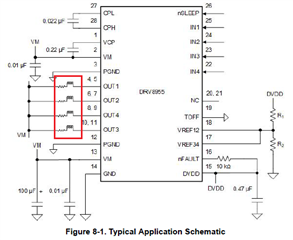
1. Model: DRV8935/DRV8955

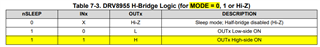
2. When IN1 is in logical "1" state, what's the OUT1 state? High or Low?

There is an issue I think it need your help to confirm..., I describe as below:

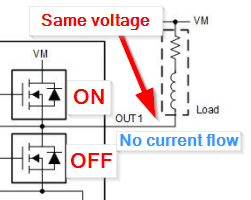
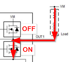
3. DRV8955 is connected to a unipolar motor, the other end of the motor coil is connected to VM.

4. IN1~4 are at low state, nSLEEP is set to logic "1", MODE is connected to GND

5. Power turned on, DRV8955 will heat up and can't work.

Our modor application:

6. One end of unipolar motor coil is connected to VM.

7. IN1~4 are active "1", idle "0".

Should I change the connection of item 6 from VM to GND to avoid the DRV8955 heat up and workable?

  • Hello,

    The following control table can be used to show expected outputs given certain inputs. 

    If IN1 = 1, then OUT1 with high side will be ON. If turning the high side on, the load should be connected from OUT to GND. If load tied to VM, then the low side FET should be turned ON.

    Best,

    David

  • I noticed that in the application circuit in the data sheet, the motor load (marked in red) has a symbol of a resistor connected in series with the coil. Does this mean that the DCR impedance of the motor coil must be lower than the maximum drive current specification?

    For example, if the coil DCR=12 ohm, it can operate under VM=24V, but if the motor is replaced with a coil DCR=0.35 ohm, it will exceed the specification and cannot be driven under the same VM conditions. Is this correct?

  • Hello,

    The resistor and inductor in series represent a simplified electrical model of a brushed DC motor. Yes, a motor with the appropriate amount of resistance must be selected so the inrush current doesn't exceed the motor driver's capability. The relationship between L and R plays a critical role in determining the rate at which current builds up during inrush and stall conditions. The L and R values can help determine the time constant  τ = L/R of the motor.

    Higher Inductance (L) → Larger τ → Slower Current Rise: The inductor resists the change more strongly, causing a slower build-up of current.

    Higher Resistance (R) → Smaller τ → Faster Current Rise: The circuit reaches its steady-state current more quickly.

    Best,

    David