Other Parts Discussed in Thread: DRV8952, DRV8962
Tool/software:
Dear TI Support Team,
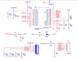
I have made a DRV8955/DRV8923 test board and tried several methods to get the motor running.
The schematic had also been previously provided for E2E review.
e2e.ti.com/.../drv8935-request-for-schematic-review
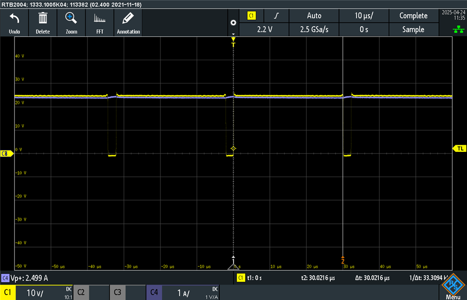
Unfortunately, the DRV8955 indicated a 'fault' when powered on. The impedance of both VREF pins to ground was only about 300 ohms, although the outputs were not short-circuited.
Could you please help check again if there is any issue in the circuit?
Or, could you provide me with a working reference schematic?
Another question: Can the DRV89x5 be used to drive a unipolar motor with a coil DCR of only 0.3 ohm?
I can provide the datasheet privately if needed.
If it's not possible to drive a motor with this specification, I think it's reasonable to consider the previous test results invalid.
Thanks!