Tool/software:
Hello,
I’m using the DRV8334EVM using DRV3233_Sensored_Trapezoidal_GUI as the DRV8334_Sensored_Trapezoidal_GUI doesn’t work for me.
The bottom bar displays “Connecting to Ti Cloud Agent…” then “Hardware connected”.
But the voltage monitors stay to 0.0V and the board doesn’t react to nSLEEP switch.
I tried File/Program device, which end in “Flash successful” but no better results after. Any idea ?
All my issues explained here are observed on the DRV8334EVM, so you can reproduce them in your lab easily.
The configuration of the DRV8334 is as follow before starting the motor spin :
| Bitfield | Value | Description |
|---|---|---|
| PWM_MODE | 0b000 | 6x PWM mode (INHx/INLx) |
| SGD_MODE | 0b00 | Smart Gate Drive with fixed peak current control. TDRVN_D is not valid and ignored. |
| SGD_TMP_EN | 0b1 | 1bSGD temperature control is enabled. |
| DEADT | 0b111 | 2000ns |
| DEADT_MODE | 0b0 | Dead time is inserted when device input (INHx or INLx) goes low. |
| DEADT_MODE_6X | 0b00 | Dead-time protection is enabled. The gate driver control signals are enforced low during the dead time period. The SPI fault flag is set and the nFAULT pin is driven low when the dead time condition is detected. |
| IDRVP_CFG | 0b0 | IDRVP register is not valid and ignored. IDRV_RATIO is used to determine IDRVP parameter. |
On the initial configuration, the register GD_CTRL2 is set at : GD_CTRL2 [1F] = 0x0717
| P | N | |
|---|---|---|
| TDRIVE | 1.036us | 1.036us |
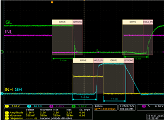
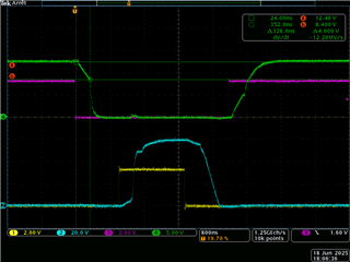
The resulting waveform are bellow, with the signals INL/GL and INH/GH displayed. Probes are placed on testpoints GLA, GHA and J9 connectors pins 1 (INHA) and 3 (INLA).
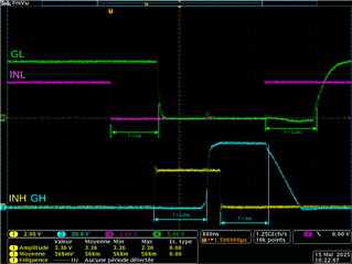
We can observe an huge propagation-delay/deadtime of ~1us between the moment the input signal switch state and the gate driver output follows command.
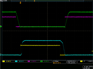
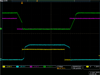
Then I test with a new configuration of GD_CTRL2 [1F] = 0x0010
| P | N | |
|---|---|---|
| TDRIVE | 0.143us | 0.143us |
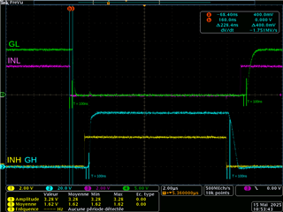
Now you can see that output follows input way better. What you could assume is that this delay is directly selected TDRIVE as the measured delay matches the settings in GD_CTRL2.
But according to the datasheet, TDRIVE is the time the IDRIVE current is applied. I don’t see why it would add a delay BEFORE driving the gates.
Bellow is the Figure 6-6 from datasheet. I added in red what I think I observe.
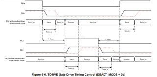
So why does it behavior like this ? I saw many explanations of TDrive on different Smart Gate Drive IC references and none of them match this behavior.
We are building a robotic BLDC driver and are planning to use the DRV8334 but so far this reference is not easy to handle as the datasheet isn't very detailed on configuration steps.
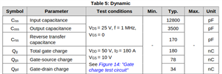
My final design will use CSD19502Q5BT mosfets. I’m planning to have ~100ns switching time for my mosfet to match EMI performances. Can you help me with what settings should I use for IDRIVE/TDRIVE/DEADT combination ? The PWM frequency will be around 50kHz to 100kHz so I can't afford >1us delays like in the first picture.
Thanks for any help,
Adrien.