Other Parts Discussed in Thread: DRV8702D-Q1, MSP430G2553, MSP-FET, MSP-EXP430G2ET, UNIFLASH, DRV8702-Q1EVM, DRV8702-Q1
Tool/software:
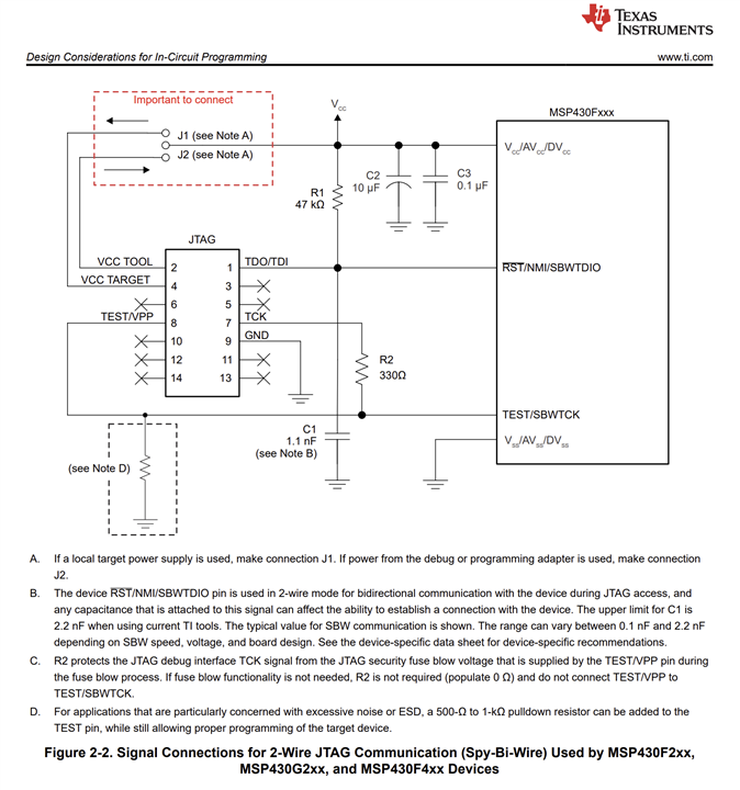
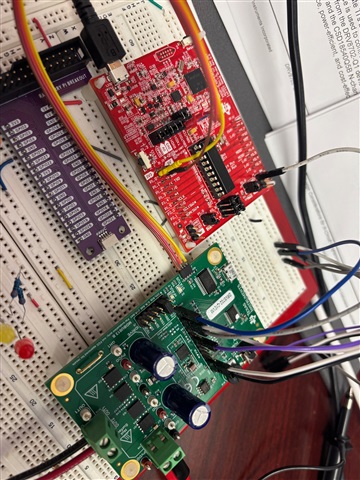
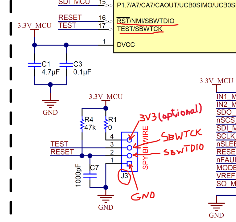
I want to drive a 30uH, 1.28 Ohms load using a regulated 12VDC power supply. The waveform is a 12.5 Hz, bipolar 50% duty cycle (ON:OFF:-ON:OFF), no high-frequency PWM. I need the load to reach max current (slightly below 9.1A) before the switch-off. I need to minimize the switch-off time and linearize it using an external active voltage clamping circuit. My plan is to program the MSP430G553 to control the H-bridge to generate such waveform and output maximum current values and protection circuit status to a Raspberry Pi 5 via UART. My understanding is that TI CCS software can be use to program and flash the MSP430G553. After full installation and updates, the CCS can not recognize neither the DRV8702D-Q1EVM board nor the MSP430G553. I need some help in: i) getting the CCS to work, configure the board so it can be discovered (if needed, or configure it for flashing), or suggestions/procedures to program the board using a different app. ii) how to configure ISENSE to provide maximum current information knowing the my peak current should be in the 9A range. Any additional information (documents, software, videos) besides the DRV8702D-Q1EVM user's guide or the DRV8702D-Q1 datasheet is greatly appreciated.