This thread has been locked.

If you have a related question, please click the "Ask a related question" button in the top right corner. The newly created question will be automatically linked to this question.

DRV8462: Motor Shorting When Enabling Drivers Via SPI

Part Number: DRV8462

Tool/software:

Hi, 

We are running into an issue with the DRV8462 driver where the motor appears to get shorted when we enable the motor driver as indicated in the title.  I will describe the context and situation, and what we have tested so far.

Project:

-We are building a custom PCB for a cutting machine that is driven by 2 bipolar steppers motors (one in the x-axis the other in the y-axis, datasheets attached at the  end of this message).

-We are using the DRV8462 motor drivers in SPI mode to take advantage of some of the features available in SPI mode.

-The microcontroller is an Arduino clone, and the firmware is a modified GRBL code (the main modification is adding SPI communication)

-Before making and designing the custom PCB, we tested with the evaluation board hooked up to an Arduino board.  The evaluation board was configured using the web based GUI, and the firmware was just the normal GRBL code.  It worked fine.

-The cutting machine is using a 48V power supply.

Current Situation:

-We have designed and made the custom board.  We tested the different parts of the circuit, and the only part that doesn't work so far is the stepper driver circuits.

-When enabling the stepper driver, we see the voltage reading on our variable power supply drastically reduce in voltage and pull excessive current - hence the motor shorting as indicated in the title.  What is also strange is that when I try to move the motor by sending it a command, the motor appears to lose power because the current draw goes to near zero and the voltage shoots back up to the set supply voltage - and the motor does not move.  I know the motor is not broken because I measured winding resistance and tested the motors on a separate machine and they work fine.  Also, I do not think the driver chip is broken because I tested with known driver chips that worked and I tested on multiple drivers/boards and was able to replicate the problem.  

-Also, when enabling the stepper driver, I hear a high pitched sound coming from the driver.

-Our code appears to be able to write to the registers via SPI because we can see the motor receive power when we enable the driver.  

-Additionally, our code appears to not read the registers via SPI because the returned data is not what we wrote to that register.

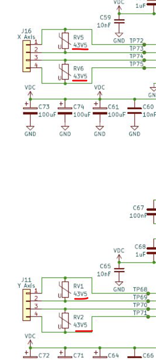
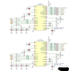
-Attached is the schematic for the motor drivers.  As you can see, the nSLEEP pin is pulled high while the nHOME, nFAULT, DVDD, and MODE pins are tied together.  

-I hooked up the evaluation board to a separate Arduino board in the same way to our circuit to see if I run into the same issue, and I was able to replicate the issue with the evaluation board.  

-I tried sequencing the start up of the motor driver where the motor driver would start in the SLEEP state and I would in sequence wake it up, then enable the motor driver.  However, the problem still persisted.

We are unsure of the next steps, so some guidance would be great.  Let me know if you have any additional questions.  Thanks in advanced!

ML23HS0P4100.pdfMS17HD6P4150.pdf

  • Hi Phillip,

    Thanks for reaching out to us via this forum. As well as thanks for the detailed description of the issue and the schematic. Overall, the schematic looks okay.

    -The cutting machine is using a 48V power supply.

    It appears that you have 43.5 V MOVs on the outputs. Please remove these MOVs and test the application. If you're using MOV's on the outputs you must have their clamping voltages > VM + two diode forward drops at the rated current. could be as much as VM + 4 V or 52 V MIN. 

    -When enabling the stepper driver, we see the voltage reading on our variable power supply drastically reduce in voltage and pull excessive current - hence the motor shorting as indicated in the title. 

    The MOVs may be shorting the outputs. I think addressing this would take care of this issue. Thank you.

    Regards, Murugavel 

  • Hi Murugavel,

    Thanks for getting back to me so quickly.  Your suggestions seems reasonable, and I also wanted to test at different input voltages before and after removing the MOVs.  Below is what I tested and what the results were:

    BEFORE removing MOVs:

    at 48V: Same thing occurs where the voltage reading on the power supply drops down to about 4.4V and pulls excess current.

    at 24V: Same thing as above.

    at 5V: Same thing as above.

    AFTER removing MOVs:

    at 48V: Same thing as above.

    at 24V: Same thing as above.

    at 5V: Same thing as above.

    Removing the MOVs appeared to have no affect.  Additionally, I noticed something else when testing.  I am only testing one driver at a time so only one motor is plugged in.  I only have the Y-axis motor plugged in.  When I send a command to move in the Y-axis, the motor does not move but I can feel the motor "jump" slightly when it goes from stop to start.  The strange part is, I can feel the Y-axis motor jump when I send a command to move in the X-axis.  Not sure if this is significant, but it did seem unexpected.  

    What else could be causing the issues i'm seeing?  Thanks in advanced.

    Best,

    Phillip

  • Hi Phillip,

    Thanks for checking and sharing the results. I'm surprised it was not the 43.5 V rated MOVs that were clamping 48 V VM voltage. I rechecked the schematic and would like you to confirm the following. I did not catch these last time. Could you also please double check the footprint used for the layout? I assume you used the TI provided footprint for the DRV8462DDWR device. Thank you.

    1. AOUT1: I noticed the schematic shows only pin-4. The device pin out requires connection pins-4, 5 and 6 together for AOUT1.
    2. AOUT2: Likewise must have pins-7, 8, 9 connected together.
    3. BOUT1: Must have pins-17, 18, 19 connected together.
    4. BOUT2: Must have pins-14, 15, 16 connected together.  
    5. PGNDA: Must have pins-3, 10 connected together.
    6. PGNDB: Must have pins-13, 10 connected together.

    Regards, Murugavel 

  • I can confirm that all the pins you mentioned are tied together from looking at the board layout and checking for continuity with a multimeter.

  • Hi Murugavel,

    Quick update on our end, we were finally able to get it to work.  There was an issue within our firmware settings that inverted the ENABLE pin.  Once we set it to the right way, it solved our issue.  Thanks!

  • Hi Phillip,

    Thank you for the confirmation. I'm also assuming you checked for shorts between pins and ruled out any other form of unexpected circuit level issues. Was this high current issue tested on multiple PCBA and all of them confirmed similar behavior? 

    A good way to cross check driver circuit would be to measure the below two currents and check for compliance. This would be with no load connected. 

    Assuming these check out we can proceed with the following debug. Let's focus with U13 first - keep U14 in sleep mode. Connect just the coil A to U13. Let's retain all the registers in default configurations except changing EN_OUT = 1b in the CTRL1 register to enable to outputs. The indexer will point to Home position electrical angle 45 °. Both coils would have 71 % of the IFS set by VREF here 1.44 A, so 71 % would be 1 A. A current probe on coil A should measure 1 A. Likewise for coil B, the current probe for coil B should also measure 1 A. Could you please check these and if possible capture coil A and coil B current waveforms? 

    Also would be useful to check the nFAULT pin voltage, if no faults it should measure the DVDD voltage level 5 V. Because the indexer will be in Home position nHOME pin would be 0 V. If nFAULT = 0 V please read FAULT and DIAG1,2 and 3 registers and share with us. Thank you.

    Regards, Murugavel 

  • Hi Phillip,

    I guess our messages crossed path. Thanks for the update. Glad you were able to get it to work. 

    There was an issue within our firmware settings that inverted the ENABLE pin.  Once we set it to the right way, it solved our issue.

    You mentioned there was a high current draw on the VM voltage. That should not have any relation to the ENABLE pin especially if it was logic 1 the outputs would be HiZ. I assume you found the root cause for the high current as well. Thank you.

    Regards, Murugavel