This thread has been locked.

If you have a related question, please click the "Ask a related question" button in the top right corner. The newly created question will be automatically linked to this question.

DRV8262EVM: Hilfe bei DRV8262EVM: Single H-Bridge + PH/EN funktioniert nicht + VREF + Strommessung

Part Number: DRV8262EVM
Other Parts Discussed in Thread: DRV8262

Tool/software:

Hallo zusammen,

ich möchte den DRV8262EVM im Single H-Bridge Mode mit dem PH/EN-Interface betreiben.
Laut Datenblatt habe ich folgende Einstellungen vorgenommen:

  • MODE1 = HIGH → Einzelne H-Brücke 

  • MODE2 = LOW → PH/EN-Schnittstelle 

Allerdings funktioniert das Ganze nicht wie erwartet – daher meine Fragen:

1. Habe ich die richtigen Pins angesteuert?

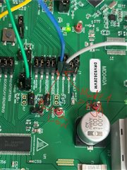
Ich habe ein Bild von meinem Aufbau angehängt, auf dem zu sehen ist, welche Pins ich auf HIGH bzw. LOW gelegt habe.

Trotz der oben genannten Einstellungen (MODE1 high, MODE2 low) zeigt der Treiber keine Reaktion.
Kann es sein, dass ich die falschen Pins geschaltet habe?
Oder muss man noch etwas Zusätzliches beachten?

(Modus 1 =  graues kabel) (Modus 2 = blaues Kabel)

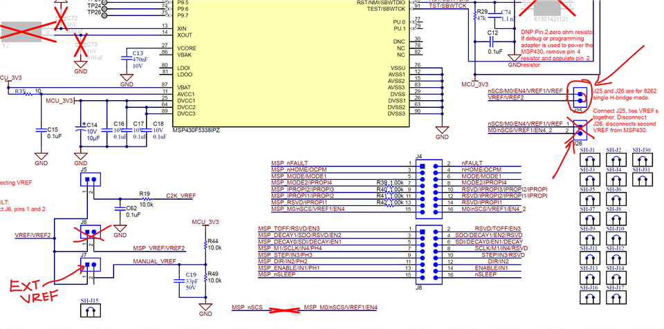
 2. Wie kann ich VREF korrekt erhöhen?

Ich möchte den maximalen Strom erhöhen, den der DRV8262 liefern darf.

Im Datenblatt steht, dass man dazu:

  • den Jumper J6 entfernen soll (um die interne Verbindung zu kappen)

  • und dann an J5 (oberer Pin) eine externe Spannung (z. B. 1,5 V oder 3,3 V) anlegen kann

Ich habe also J6 entfernt und 3,3 V an J5 angelegt – aber es passiert nichts.
Die Spule zieht weiterhin kaum Strom, es wirkt so, als würde VREF ignoriert oder blockiert werden.

Arrow right️ Sind das überhaupt die richtigen Pins, um VREF zu entkoppeln und manuell zu setzen?

 Muss ich zusätzlich etwas beachten (z. B. Pull-Down, Schutzwiderstand, Aktivierung über Software)?

 Beobachtung

Wenn ich testweise MODE2 = HIGH setze (also den Treiber in den IN/IN-Modus bringe),
bekommt die Spule ein Ausgangssignal – also der Treiber reagiert grundsätzlich.

Aber es fließen nie mehr als ca. 0,5 A, selbst bei einer Versorgungsspannung von 5 V, 9 V oder 12 V.

Arrow rightLiegt das wirklich an VREF?
Wird der Strom intern so stark begrenzt, weil VREF zu niedrig ist?
Oder könnte auch etwas anderes dafür verantwortlich sein?

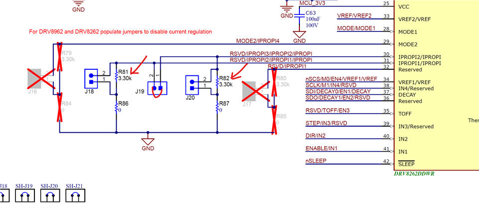
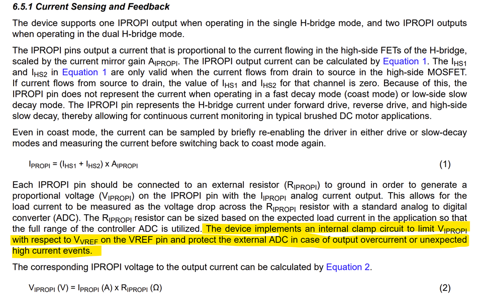
3. Strommessung – IPROPI

Ich möchte die Stromaufnahme der Spule über den IPROPI-Pin auslesen und mit einem STM32 messen.

Laut Datenblatt gibt es im Single H-Bridge Mode zwei IPROPI-Pins, die man miteinander verbinden soll.

Arrow rightWelcher PIN auf dem EVM-Board ist das konkret?
Arrow rightKann ich diesen direkt mit einem ADC-Eingang (z. B. A0) meines STM32 verbinden?
Arrow rightBrauche ich einen Spannungsteiler oder ist das Signal bereits angepasst?
Arrow rightMuss ich einen externen Shunt-Widerstand verbauen oder ist der im Board bzw. im IC integriert?

Ich freue mich über jede Hilfe – insbesondere wenn jemand den Treiber schon erfolgreich in dieser Konfiguration betrieben hat.

Viele Grüße

Dennis Formisano


  • Hi,

    Thank you for your questions. Our expert will feedback to you within a couple of days.

  • Hi Dennis,

    Thank you for reaching out to us via this forum.

    1. Did I control the correct pins?

    I have attached a picture of my setup showing which pins I have set to HIGH and LOW.

    Despite the settings mentioned above (MODE1 high, MODE2 low), the driver shows no response.
    Is it possible that I've connected the wrong pins?
    Or is there something else I need to consider?

    MODE1 and MODE2 pins looks correct in the picture you shared. See below from the EVM User's Guide page-45.

    According to the datasheet, I have the following settings:

    • MODE1 = HIGH → Single H-bridge 

    • MODE2 = LOW → PH/EN interface 

    This is correct for Single H-bridge and PH/EN control mode.

    2. How can I increase VREF correctly?

    I would like to increase the maximum current that the DRV8262 can deliver.

    The data sheet states that you need to:

    • remove jumper J6 (to cut the internal connection)

    • and then apply an external voltage (e.g. 1.5 V or 3.3 V) to J5 (upper pin)

    So I removed J6 and applied 3.3 V to J5, but nothing happened .
    The coil still draws barely any current, and it seems as if VREF is being ignored or blocked.

    For external VREF connection in Single H-bridge mode both VREF1 and VREF2 must be tied together. In the EVM this means open J26 and shunt J25 - see below. Remove J6 to cut VREF2 from the MSP430 DAC. You should apply external VREF voltage 0 to 3.3 V via pin-1 of J7 or J6 or J5. You had this correct. Perhaps the missing piece was J25 shunt (remove J26). 

    observation

    If I set MODE2 = HIGH for testing purposes (i.e. put the driver into IN/IN mode),
    the coil receives an output signal – so the driver basically reacts.

    But never more than about 0.5 A flows , even with a supply voltage of 5 V, 9 V or 12 V.

    Is this really due to VREF?
    Is the current being limited internally because VREF is too low?
    Or could something else be responsible?
    Which pin on the EVM board is this exactly?

    The EVM has two 3.3 kΩ RIPROPI resistors in parallel (1.65 kΩ) after J19 shunt is installed for Single H-bridge operation. See below. With external VREF = 3.3 V (VREF MAX) the current through IPROPI would be 3.3 / 1650 = 2 mA. The specified AIPROPI for this device is 212 μA / A. The output current would be regulated at 2E-3 / 212E-6 = 9.4 A


    3. Current measurement – ​​IPROPI

    I want to read the current consumption of the coil via the IPROPI pin and measure it with an STM32 .

    According to the datasheet, in single H-Bridge mode there are two IPROPI pins that should be connected together .

    Can I connect it directly to an ADC input (e.g., A0) on my STM32?

    The IPROPI is connected to the MSP430 ADC inputs via an RC LPF 1 kΩ  and 0.1 μF. You can have an RC LPF that suits your requirements.  


    Do I need a voltage divider, or is the signal already adjusted?

    The IPROPIx has internal clamp to limit the voltage on this pin to VREF voltage. VREF range is 0.05 V to 3.3 V. With MAX 3.3 V the input to an ADC will be clamped to 3.3 V. Generally a voltage divider may not be required. This would depend on the ADC input voltage range. The onboard MSP430 ADC input range is 0 to 3.3 V. 

    Do I need to install an external shunt resistor, or is it integrated into the board or IC?

    Current sensing is integrated in the device. No external shunt resistors are required.

    See below image snippet for EVM configuration.   

    Regards, Murugavel