Other Parts Discussed in Thread: PMP22764, PMP
Tool/software:
Hi
Could you help check the below LM51551 schematic and any need to adjust
Vin 20v to 56v 1.4A
This thread has been locked.
If you have a related question, please click the "Ask a related question" button in the top right corner. The newly created question will be automatically linked to this question.
Hi Gareth,
Could you please attach the filled out https://www.ti.com/tool/download/SNVC224 to this thread? This would be the most efficient workflow for us to do a schematic review.
Best regards,
Mounika
Hi Mounika
It has been filled out. If it is a flyback architecture, do we use the same tool?
Thanks
LM5155_56_Quickstart_Calculator_for_Boost_Converter_Design_V1_1_1 的複本.xlsx
Hi Gareth,
I am extremely sorry. That was my mistake to send the wrong tool
https://www.ti.com/tool/download/SNVC240 - This is for flyback.
Best regards,
Mounika
Hi Gareth,
Please accept my apologies for sending the wrong tool. Could you please send the attached form for flyback.
Best regards,
Mounika
Hi Mounika,
Please check the excel result and new schematic. If anything we have to modify? Thanks.
Regards,
Gary
lm51551_45w_0610.pdfLM5155_56_Excel_Quickstart_Calculator_for_Flyback_Regulator_Design_amttran_45W.xlsx
Hi Gary,
Thank you for your patience and attaching the QS calculator.
1. Please make sure that if the transformer can handle the high current.
2. Please connect the Feedback divider circuit before the output filter.
Otheriwse, the schematic looks good.
Best regards,
Mounika
Hi Mounika,
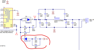
1. Customer choose another transformer as attached. It's inductance is small (0.8uH, smaller than the suggestion in calculator) Is it ok for their design? Or they have to redesign their transformer to CCM mode?
LM5155_56_Excel_Quickstart_Calculator_for_Flyback_Regulator_Design_amttran_45W_0612.xlsx
2. What's your meaning about divider's position? Here?
Thanks and regards,
Gary
Hello Gary,
With this magnetizing inductance, the peak to peak current on the primary side is almost 30A, so mostly this flyback will work in DCM, I think. If this is a problem for the customer, is system dependent. But it is possible that the energy available on the output is not enough.
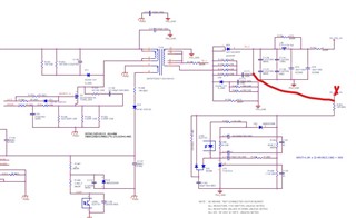
Yes, you have the right connection in your drawing. Otherwise the filter can cause instable behavior.
Best regards,
Brigitte
Hi Brigitte and Mounika,
1. About the feedback point, my customer check PMP22764 as reference. Can we know why they put the feedback path after the filter?
2. In this reference design Pin 8/9/1/11 in transformer is linked with D1_K. Why those nodes need to be link together?
And the attached filed is spec. about new transformer. Please help to check it too. Thanks.
Regards,
Gary
Hi Gary,
1. It is possible that the designer of this PMP took the filter into accound when calculating the loop. Then it is ok to connect the FB like this.
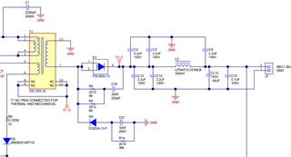
2. It is mentioned in the schematic, that the NC pins are connected for thermal and mechanical reasons. so it is not always necessary.
The transformer looks good to me. But please make sure it does not saturate with the maximum current. I cannot read the saturation current out of the datasheet, so please check with you vendor. the max primary current will be about 15A.
Best regards
Moritz
Hi Gery,
this is called a snubber. See also:
https://www.ti.com/lit/ta/ssztbc7/ssztbc7.pdf
https://www.ti.com/lit/ta/ssztcv6/ssztcv6.pdf
Best regards,
Stefan