This thread has been locked.

If you have a related question, please click the "Ask a related question" button in the top right corner. The newly created question will be automatically linked to this question.

DRV8262EVM: geringe Last System funktioniert, hohe Last System bricht zusammen

Part Number: DRV8262EVM
Other Parts Discussed in Thread: DRV8262,

Tool/software:

Hallo ich habe mich an folgendem Thread orientiert: 

1. Did I control the correct pins?

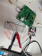
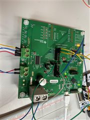
I have attached a picture of my setup showing which pins I have set to HIGH and LOW.

Despite the settings mentioned above (MODE1 high, MODE2 low), the driver shows no response.
Is it possible that I've connected the wrong pins?
Or is there something else I need to consider?

MODE1 and MODE2 pins looks correct in the picture you shared. See below from the EVM User's Guide page-45.

According to the datasheet, I have the following settings:

  • MODE1 = HIGH → Single H-bridge 

  • MODE2 = LOW → PH/EN interface 

This is correct for Single H-bridge and PH/EN control mode.

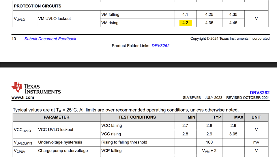
2. How can I increase VREF correctly?

I would like to increase the maximum current that the DRV8262 can deliver.

The data sheet states that you need to:

  • remove jumper J6 (to cut the internal connection)

  • and then apply an external voltage (e.g. 1.5 V or 3.3 V) to J5 (upper pin)

So I removed J6 and applied 3.3 V to J5, but nothing happened .
The coil still draws barely any current, and it seems as if VREF is being ignored or blocked.

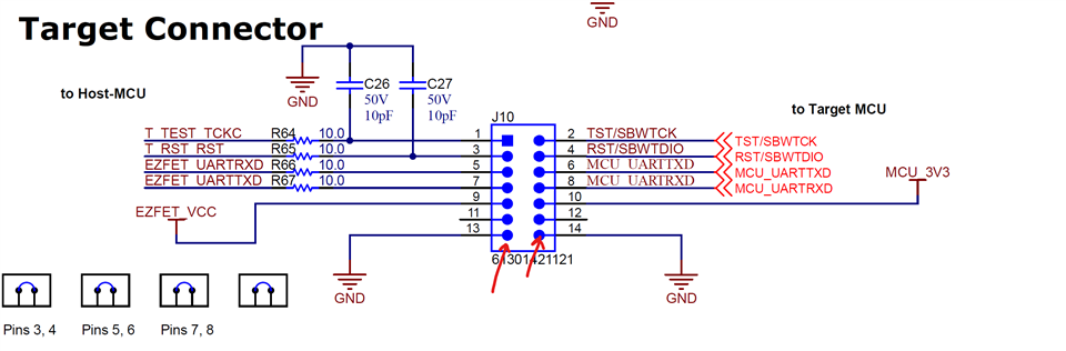
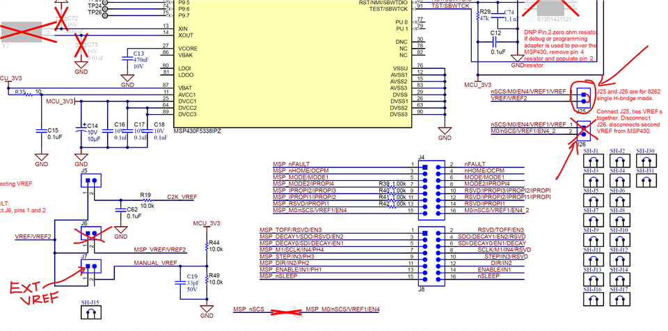
For external VREF connection in Single H-bridge mode both VREF1 and VREF2 must be tied together. In the EVM this means open J26 and shunt J25 - see below. Remove J6 to cut VREF2 from the MSP430 DAC. You should apply external VREF voltage 0 to 3.3 V via pin-1 of J7 or J6 or J5. You had this correct. Perhaps the missing piece was J25 shunt (remove J26). 

observation

If I set MODE2 = HIGH for testing purposes (i.e. put the driver into IN/IN mode),
the coil receives an output signal – so the driver basically reacts.

But never more than about 0.5 A flows , even with a supply voltage of 5 V, 9 V or 12 V.

Is this really due to VREF?
Is the current being limited internally because VREF is too low?
Or could something else be responsible?
Which pin on the EVM board is this exactly?

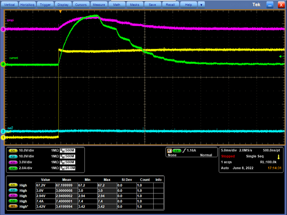
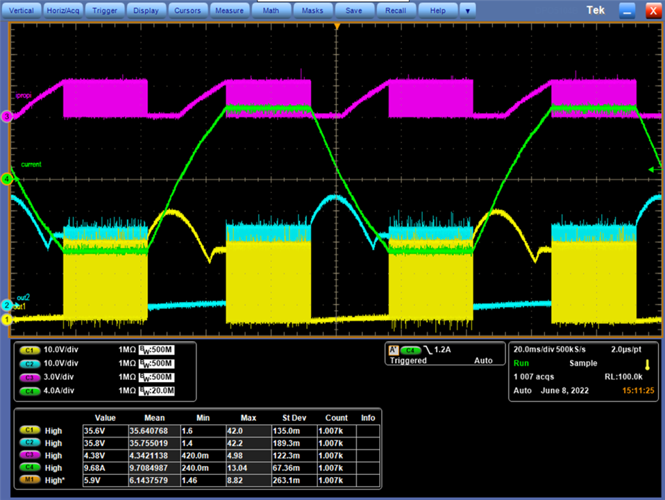
The EVM has two 3.3 kΩ RIPROPI resistors in parallel (1.65 kΩ) after J19 shunt is installed for Single H-bridge operation. See below. With external VREF = 3.3 V (VREF MAX) the current through IPROPI would be 3.3 / 1650 = 2 mA. The specified AIPROPI for this device is 212 μA / A. The output current would be regulated at 2E-3 / 212E-6 = 9.4 A

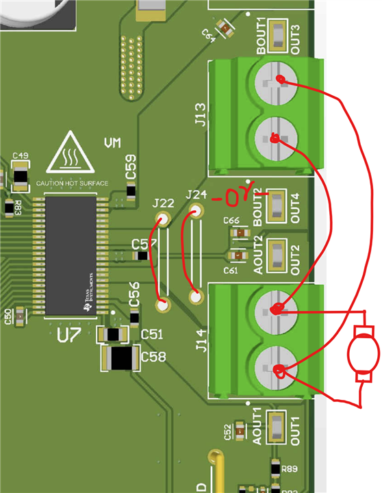
Nachdem ich die Einstellung vorgenommen habe hat sich folgendes Problem ergeben:

Wenn ich an J14 eine Diode anschließe fängt diese an zu leuchten. Ich kann auch die Eingangsspannung beliebig ändern. 

Falls ich nun einen E-Motor oder eine Spule, sprich eine hohe Last anschließe, kann ich nicht mehr als 4V Eingangsspannung an J12 einstellen. Sobald ich mehr als 4V einstelle fängt das Board an zu piepsen und die Warnleuchte D7 leuchtet auf.

Deshalb meine Frage wieso funktioniert die Einstellung für geringfügige Lasten, aber bei hohen Lasten bricht das System zusammen?

Besten Dank!

  • Hi Eduard, 

    Thanks for your post.

    After I made the settings, the following problem occurred:

    If I connect a diode to J14, it starts to light up. I can also change the input voltage as desired. 

    If I now connect an electric motor or a coil, i.e. a high load, I can't set an input voltage of more than 4V at J12. As soon as I set it above 4V, the board starts beeping and the warning light D7 lights up.

    So my question is why does the setting work for low loads, but the system crashes under high loads?

    What are the characteristics of the electric motor? It appears, the inrush current was very high leading to an over current fault indicated by D7 (nFAULT = 0). You could try reducing the VREF voltage to 1 V and observe the behavior with the DC motor at the output. The board does not have any beeper. Was the beeping sound from the motor? 

    The device has an UVLO under voltage lock out feature. Below the MIN rising voltage the device will be non-functional - no output. Above MIN rising the device will have a POR power on reset and the internal digital control will be functional at this point. 


    From the previous discussion you were using the two H-bridges in parallel. Be sure make the correct parallel connection. I'm mentioning this because J13 is flipped. See below for having the correct parallel mode connection. I think you have the correct connection else an LED on J14 would not have worked. That leaves us with a high inrush current issue. Can we get a capture of the load current waveform? Thank you.

    Regards, Murugavel 

  • Sehr geehrtes Team,

    vielen Dank zunächst für Ihre bisherigen Rückmeldungen und Ihre Unterstützung.

    Leider besteht das Problem weiterhin. Im Folgenden finden Sie eine Beschreibung unseres aktuellen Aufbaus und der beobachteten Symptome.

    Wir verwenden ein STM32F446RE-Board mit folgender Pin-Konfiguration:

    c
    KopierenBearbeiten
    HAL_GPIO_WritePin(GPIOB, GPIO_PIN_5, GPIO_PIN_SET); // IN1 aktivieren
    (PH) HAL_GPIO_WritePin(GPIOB, GPIO_PIN_4, GPIO_PIN_SET); // SLEEP aktivieren
    HAL_GPIO_WritePin(GPIOB, GPIO_PIN_10, GPIO_PIN_SET); // MODE1 = HIGH
    HAL_GPIO_WritePin(GPIOA, GPIO_PIN_8, GPIO_PIN_RESET); // MODE2 = LOW
      HAL_TIM_PWM_Start(&htim2, TIM_CHANNEL_2); // PWM auf IN2 (EN)

    Der DRV8262EVM befindet sich im PH/EN-Steuermodus (MODE1 = HIGH, MODE2 = LOW) sowie im Single-H-Bridge-Modus.
    Zur Nutzung im Parallelbetrieb haben wir OUT1 mit OUT3 sowie OUT2 mit OUT4 physisch verbunden, wie im Datenblatt empfohlen.


    Beobachtungen:

    • Als Last haben wir sowohl einen einfachen Elektromotor als auch eine Spule getestet.
      In beiden Fällen reagiert die Last nicht wie erwartet.

    • Eine einfache LED als Last funktioniert hingegen problemlos.

    • Die GND-Verbindung vom DRV8262EVM zum STM32 erfolgt aktuell über ein Breadboard.

    • Bei Systemstart ist ein hochfrequentes Piepsen hörbar, obwohl das PWM-Signal mit 20 kHz erzeugt wird.

    • Bei niedrigem Duty Cycle (z. B. 2 %) fließt ein Strom von bis zu 3 A, und der Aktuator bewegt sich kurz.
      Ab einem Duty Cycle von ca. 50 % steigt nur noch die Spannung, Strom fließt keiner mehr, und das System beginnt zu fiepen.

    • Der Strom bleibt sonst bei 0 A, und erst ab ca. 4 V Eingangsspannung leuchtet die Status-LED D7 auf dem Treiberboard.


    QuestionFragen und mögliche Ursachen:

    1. Könnte die GND-Verbindung über das Breadboard zu einem Spannungsabfall führen, der die Funktion stört?

    2. Ist es normal, dass bei höherem Duty Cycle kein Strom mehr fließt, aber bei extrem niedrigem Duty Cycle die Last stark reagiert?

    3. Könnte der beobachtete Stromverlauf auf eine inkorrekte VREF-Konfiguration oder interne Strombegrenzung zurückzuführen sein?

    4. Deutet das Piepsen trotz 20 kHz PWM-Frequenz auf eine interne Schwingung, Taktung oder Fehlfunktion im Treiber hin?

    5. Ist es möglich, dass der Treiber bereits beschädigt wurde, da wir zu Beginn im Single-H-Bridge-Modus gearbeitet haben, aber die Ausgänge OUT1/3 und OUT2/4 noch nicht verbunden waren?


    Wir wären Ihnen sehr dankbar, wenn Sie unseren Aufbau prüfen und uns gezielte Hinweise geben könnten, insbesondere zu den Punkten GND-Verbindung, Stromverhalten bei verschiedenen Duty-Cycles sowie möglicher Schutzmechanismen oder Beschädigungen am Treiber.

    Vielen Dank im Voraus für Ihre Unterstützung.

    Mit freundlichen Grüßen
    Dennis Formisano

  • Hi Dennis,

    Sorry to hear you are still facing issues with driving a motor load with one of our DRV8262EVM setup. 

    We tested both a simple electric motor and a coil as loads .
    In both cases, the load did not respond as expected.

    If I understood correctly this issue was only when you connected with an external MCU to control the EVM. For the same actuator it works as expected with the on-board MCU and the GUI in single H-Bridge mode. Please confirm.

    Could the GND connection via the breadboard cause a voltage drop that would disrupt the function?

    While electrically it may be correct because you are using not so thick gauge wires I'd recommend the external MCU GND connection like so - see below. The bottom two legs of this header is board GND / digital GND. This will allow you to keep the VM power supply GND separate and avoid potential cross talk.


    Is it normal that at higher duty cycles no current flows, but at extremely low duty cycles the load reacts strongly?

    This is not expected behavior. We've tested Single H-Bridge mode operation with a high current BDC motor and solenoid with VM = 48 V supply no issues. These drivers are currently used in similar applications world-wide.

    Could the observed current waveform be due to an incorrect VREF configuration or internal current limiting?

    Were referring to the on-chip current regulation? Could please share the current waveform?

    Does the beeping despite a 20 kHz PWM frequency indicate internal oscillation, clocking, or a malfunction in the driver?

    In my experience if the OCPM is set for auto-retry and the system inrush current is too high (low inductance low resistance load) OCP (overcurrent protection) and retry (tretry = 4.1 ms would cause an audible tone of 244 Hz (1/4.1 ms). This also would light up LED D7. If the OCPM is set for latched then this tone would not be exhibited, the outputs will become HiZ at the first OCP trip point. 

    Is it possible that the driver has already been corrupted because we started working in single H-bridge mode but the outputs OUT1/3 and OUT2/4 were not yet connected?

    It is not possible to damage the driver for this specific reason. However, if this issue persists it is possible the driver was damaged for some other reason especially with VM = 48 V. For example when the load was disconnected when the outputs were enabled an inductive kickback voltage on OUTx pins could exceed abs max. level for a short duration potentially damaging the device. Under normal circumstances even with an open load driving the device will not get damaged.

    See below example VM = 65 V, 100 % duty cycle input drive DRV8262 in Single H-Bridge mode driving a 65 V BDC motor:

    Green trace is the motor current, pink is the IPROPI, yellow is OUT1,3 and blue is OUT 2,4. You can notice the high inrush current and as the motor spins faster and faster its BEMF increases and the current settles down to a steady run current. This is typical of a BDC motor. If the inrush is too high and the current regulation is not set to limit inrush to be below OCP trip point it is possible for OCP to kick in and manifest similar to your observation. Only way to understand this would be to do an oscilloscope capture of the load current or if you don't have a current probe you can look at the IPROPI output (similar to the pink trace). You want to trigger the oscilloscope with the nFAULT pin if D7 LED comes on every time you drive the load. This will allow you capture the current and voltages at the nFAULT falling edge.

    See below example VM = 24 V, 100 % duty cycle input DRV8262 in Single H-Bridge mode driving a 24 V Solenoid with current regulation enable:

    Green trace is the solenoid current toggled back and forth in both directions, pink is the IPROPI, yellow is OUT1,3 and blue is OUT 2,4, 30 % MIxed decay, TOFF = 24 us. You can see the inductive voltage on OUTx - the bumps. As well as the OUTx voltage chopping for current regulation. 

    These two captures were taken by driving the DRV8262 inputs with external control. These were done prior to qualifying the device for manufacturing. Thank you.

    Regards, Murugavel