This thread has been locked.

If you have a related question, please click the "Ask a related question" button in the top right corner. The newly created question will be automatically linked to this question.

DRV8962: Do we need additional inductor and RC to drive a large voice coil motor?

Part Number: DRV8962

Tool/software:

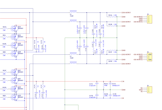
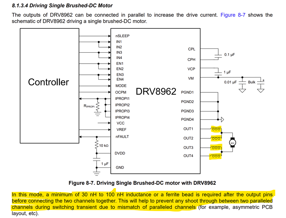
Hi, we are now using DRV8962 to drive a large voice coil motor (300uH, 1Ohm) with 15A peak and 6A RMS, the engineer recommended that connect a 4.7uH inductor in series before driving the motor, What the use of this inductor and do we really need this small inductor?

BTW, what's the use of the shunt RC in series?

Thanks!

  • Hi Benyuan,

    Thanks for your question.

    the engineer recommended that connect a 4.7uH inductor in series before driving the motor, What the use of this inductor and do we really need this small inductor?

    Those small inductors are usually used for slowing down fast inrush currents for low inductance loads. The RC circuit is a snubber circuit typically used if there is ringing or oscillations of voltage during switching. See this FAQ post.

    What the use of this inductor and do we really need this small inductor?

    If the load has sufficient inductance these additional small inductors are not necessary. These may be helpful when there is a short circuit in the output. For normal operation these are not required.

    we are now using DRV8962 to drive a large voice coil motor (300uH, 1Ohm) with 15A peak and 6A RMS

    What is the VM voltage used. What is the current profile requirement? What is the shape of the current from the moment coil is energized including the duration of the 15 A peak. 6 A RMS means 8.5 A amplitude. The DRV8962 cannot support this level of current. See below the overcurrent limits for the two packages of this device.

    Assuming good PCB design and using DDW package for the DRV8962 and VM = 48 V each half-bridge may be able to support a max of around 2.5 A continuous DC current no PWM switching or around 2 A continuous current with 20 kHz PWM switching. How do you plan to drive 6 A RMS with the DRV8962 - the complete output circuit with the load and power supply? Thank you.

    Regards, Murugavel 

  • Thank you. We use the IRF6665 circuit recommended by infineon, which we use a class-D amplifier to drive a voice coil motor.

    In terms of "sufficient inductance", how big is it as sufficient? is 300uH enough for ignoring a 4.7uH inductor?

    We used a drv8432 for such application, and drv8962 is considered as a replacement when drv8432 goes obselete. The PWM frequency should be larger than 200KHz at least (and preferrable 500KHz as DRV8432). So under higher PWM frequency, for example 200KHz maximum for DRV8962, the RMS current at 36V/24V supply would be  much lower than 2A right? we can use PTBL mode of DRV8962 for larger current rating.

  • Hi Benyuan,

    Thanks for the additional information, especially PBTL type configuration which was not mentioned in the first post. Discreet FET based design have different characteristics and behavior compared to integrated FETs, for example rise time fall time. The discreet design may have very fast rise and fall time requiring the RC snubber shown. Such RC also increases the switching losses in integrated design and heat up the IC. You may have to reduce the capacitor values if the IC tends to overheat.

    we can use PTBL mode of DRV8962 for larger current rating.

    Keeping PBTL mode connection in context, see below information from page-34 of the datasheet. In this use case series inductors are recommended before the parallel connection of the outputs. The purpose is mentioned by the highlighted sentences. This inductor is not related to the load inductance and must not be ignored. 

    For individual half-bridge connection this series inductor is not needed. The di/dt via an inductive load can be calculated using generic formula for an inductor, V = L (di/dt). Between 300 μH and 304.7 μH the difference would be negligible in their di/dt results. 

    So under higher PWM frequency, for example 200KHz maximum for DRV8962, the RMS current at 36V/24V supply would be  much lower than 2A right? we can use PTBL mode of DRV8962 for larger current rating.

    This can be calculated using the formulae in page-26, 8.1.1.2.1 Power Loss Calculations section of the datasheet. For BTL configuration total power dissipation would be 2x PHB. You want to keep the junction temperature around 80 °C to keep sufficient margin for thermal shutdown as well as longevity of the PCB components. Based on this design you can calculate the maximum continuous current that can be used.  

    Regards, Murugavel