Other Parts Discussed in Thread: DRV8262,
Tool/software:
Subject: DRV8262 – Jumper/Solder Bridge Configuration for STM32 + VREF + IPROPI Setup
Hi everyone,
I'm using the DRV8262 in single H-bridge mode, and I'm trying to use it together with an STM32 to measure the coil current via the IPROPI output.
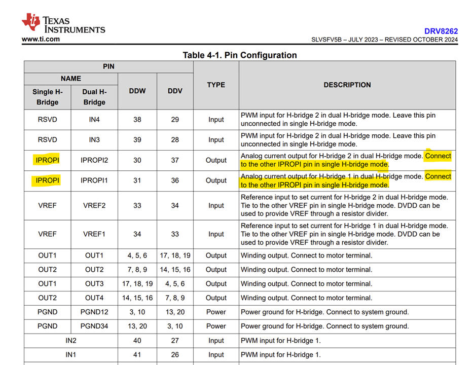
According to the datasheet, IPROPI1 and IPROPI2 should be connected in this mode – so I’ve made some changes to the solder jumpers and bridges on the board accordingly.
I’ve also manually set VREF to 1.65 V using a voltage divider, and I'm reading the IPROPI signal via an ADC on the STM32.
 My current setup:
-
I’m controlling the H-bridge from my STM32 via IN1/IN2
-
VREF is manually supplied with 1.65 V via a voltage divider
-
I’m currently only reading one IPROPI pin via ADC (the other is not connected)
-
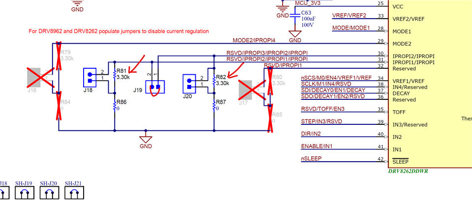
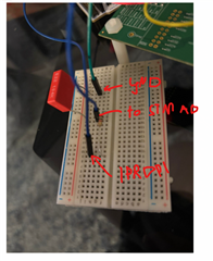
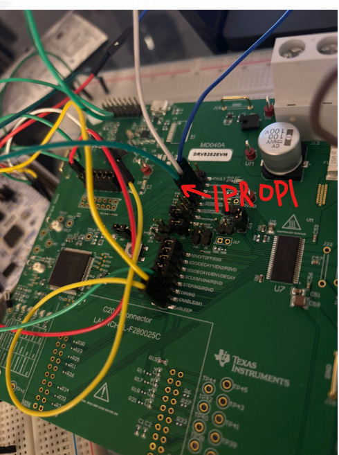
I’ve modified some solder jumpers (opened/closed) to try to configure this setup
-
I've attached a photo showing all current jumper/solder bridge configurations
 Questions:
-
Is this the correct way to configure the board if I want to:
-
Use STM32 to control the H-Bridge
-
Manually set VREF
-
Read current via IPROPI using ADC
-
-
Do I really need to connect IPROPI1 and IPROPI2 together in single H-bridge mode?
-
If yes, which ones are the correct physical pins on the board that correspond to IPROPI1 and IPROPI2?
-
Can someone please take a look at the attached image and confirm if the jumpers look correctly set for this configuration?
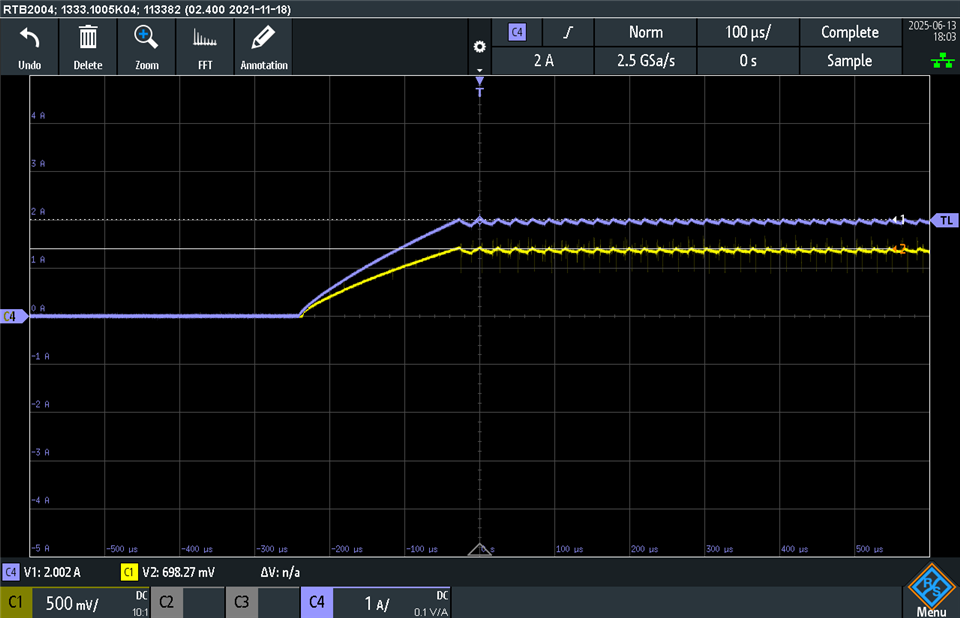
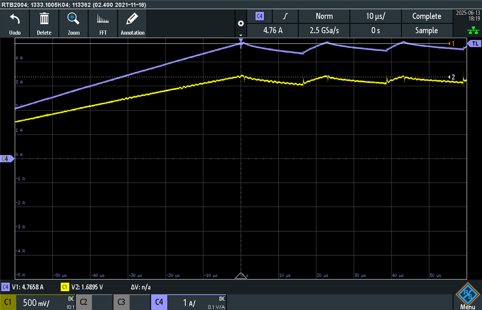
Currently, when I drive 5 A, I get only around 400–500 as raw ADC value, which seems too low based on the expected gain.
Thanks in advance for any help or clarification!
Best regards,
Dennis
Additional Information Regarding IPROPI Measurement (J19 Jumper Installed):
We would like to provide a follow-up regarding our current IPROPI measurement setup.
We have verified that the Jumper J19 is installed on the DRV8262EVM, which—according to the EVM documentation—connects IPROPI1 and IPROPI2 internally via two 3.3 kΩ resistors, resulting in a combined 1.65 kΩ resistance to GND. The resulting voltage is routed directly to the STM32F446RE ADC input A0.
Despite this seemingly correct configuration, the measured values are significantly lower than expected. Here are the details of our setup and results:
-
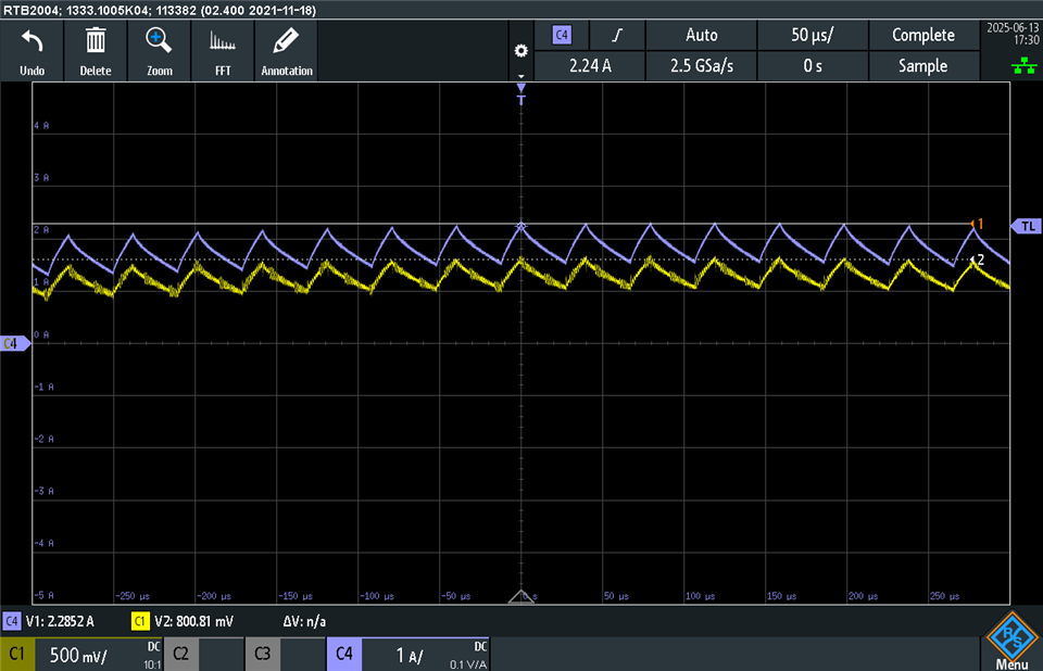
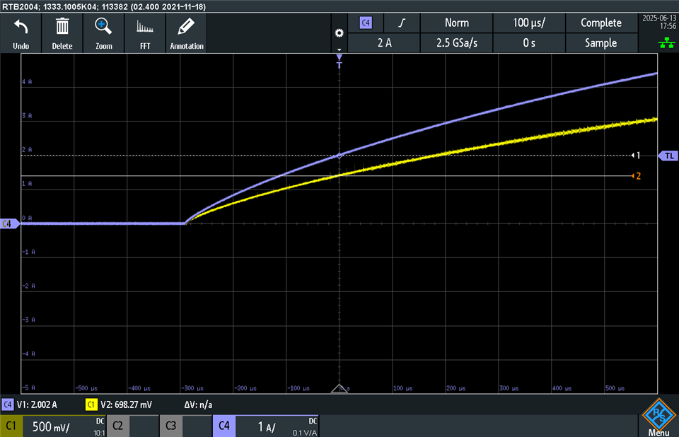
Voltage measured at A0 (IPROPI output) with a multimeter: 0.378 V
-
Current shown by the power supply (CV mode): 2.21 A
-
Supply voltage: 5.2 V
-
Raw ADC value (12-bit) read by the STM32: approximately 300–400
Based on the formula from the DRV8262 documentation:
UIPROPI=ILOAD⋅212 μA⋅1.65 kΩ=ILOAD⋅0.35 VU_{\text{IPROPI}} = I_{\text{LOAD}} \cdot 212\ \mu\text{A} \cdot 1.65\ \text{kΩ} = I_{\text{LOAD}} \cdot 0.35\ \text{V}UIPROPI=ILOAD⋅212 μA⋅1.65 kΩ=ILOAD⋅0.35 V
we would expect a current of 2.21 A to produce around:
U=2.21⋅0.35=0.77 VU = 2.21 \cdot 0.35 = 0.77\ \text{V}U=2.21⋅0.35=0.77 V
→ However, we consistently measure only 0.378 V, which would correspond to roughly 1.08 A – only about half the expected value.
This result is consistent both with the multimeter reading and the ADC value, which suggests the scaling is working correctly, but the IPROPI signal is not delivering the expected voltage for the actual load current.
We kindly ask if there is any known issue or configuration detail we might be missing that could cause this discrepancy. Is it possible that the IPROPI current mirror is not scaling symmetrically in single H-bridge mode, or could this be related to an internal current limit despite VREF being set to 1.65 V (externally applied)?
Thank you again for your continued support.
Best regards,
Dennis Formisano