


Other Parts Discussed in Thread: STRIKE,
Tool/software:
Team,
There is R/C filter added at nFAULT output as below circuitry. However, when capacitance is up to 1uF, the nFault pin cannot be pulled down successfully. When 1nF is used, it's ok.
We'd like to know the sinking current capability at nFAULT pin. and what recommendation for R/C filter? Thanks
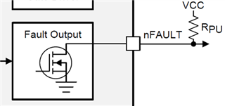
R/C circuitry for FAULT pin:
The main purpose of the R/C circuitry is to do the filter function against the ESD +/-8KV air and +/-6KVds contact strike on e-scooter motor drive.
GD_FAULT_C is connected to MCU I/O pin.
Pulled-high resistor of the PG pin is 10K-Ohm.

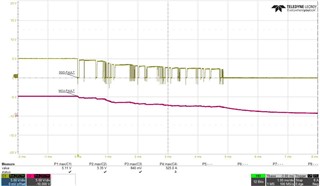
C21: 1uF => NG
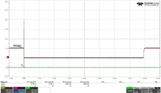
C21: 1nF => Pass
Regards
Brian


