DRV8243H-Q1EVM: Motor drivers forum

Part Number: DRV8243H-Q1EVM
Other Parts Discussed in Thread: PCF8574, ADS1115, DRV8243-Q1

Tool/software:

Hello Joshua, months ago I opened a thread "DRV8243H-Q1EVM: general configuration & layout revision".

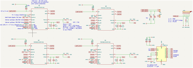
I build some pcb boards according to schema provided in that thread. I'm testing them now but I'm facing some issues.

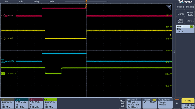
Looks like the IC is not receiving reset pulse correctly.

I'm using 4 pins of a pcf8574 to generate 3,3v SLEEP signals and 4 pins to read FAULTs.

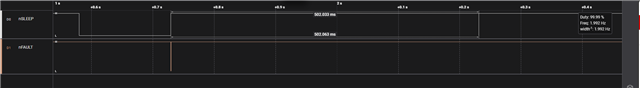
During power on this sequence if followed:

- put pcf8574 sleep pin high,

- after 500 mili sec aprox execute the reset pulse (low) 

- after 30 micro seconds put high again. 

About i2c bus:

there is one ads1115

total pull up resistance 4,7K 

Can pcf8574 cause problems?

Thanks

  • Hi Juan,

    Can a capture of the nFAULT, nSLEEP, and VM pin be provided during the reset pulse? I want to make sure that the nFAULT pin is toggling or not to make sure the nSLEEP reset pulse is being registered by the device. If the nFAULT pin does toggle, then the device may be experiencing a different fault and is awake and seeing the votltage on OUT1 and OUT2 and the output current would be helpful.

    Regards,

    Joshua

  • Hello Joshua, thanks for feedback.

    Unfortunately I don't have testpoints available to do this.

    But I can confirm that pcf8574 inputs are reading fine and outputs are getting high.

    Let's say for Mosfet 4 (M4) there is an output P3 (sleep) and input P7 (fault).

    Then run a sequence according to code below:

    mosfetHandshakeMaster(P3);
    mosfetResetMaster(P3);
    
    nFault1Actual = pcf8574.digitalRead(P4);
    nFault2Actual = pcf8574.digitalRead(P5);
    nFault3Actual = pcf8574.digitalRead(P6);
    nFault4Actual = pcf8574.digitalRead(P7);
    
    void mosfetHandshakeMaster(uint8_t nSleep){
    
        pcf8574.digitalWrite(nSleep, HIGH);
        delay(500);//500 mili seconds 
     
      }
    
    void mosfetResetMaster(uint8_t nSleep){
    
        pcf8574.digitalWrite(nSleep, LOW);
        delayMicroseconds(30);// 30 micro second LOW
        pcf8574.digitalWrite(nSleep, HIGH);
        delay(500);
       
      }

    The only mosfet showing changes is M4.

    During "mosfetHandshakeMaster(P3)" P7 goes to LOW, but never gets HIGH again.

    No changes on P4, P5 nor P6.

    Almost the same if I do the sequence for M1 (P0), M2 (P1), M3 (P2).

    Pin mode left float --> PWM mode

    A small Stanley scd 12v brushed motor connected to output 1 (M+) / output 2 (M-).

    0v between M+ M-..

    Best regards,

    Juan 

  • Hi Juan,

    1. I'm having a bit of trouble following how the pcf8574 is connected to multiple DRV8243s. Can a block diagram be provided?
      1. also just to make sure, none of the DRV8243-Q1 are working correct, the nFAULT pin on all of them do not recover?
    2. Is it possible to probe the voltage at the VM pin as close to the pin as possible to make sure it is higher than the VM UVLO threshold?
    3. Can you measure the voltage on the IPROPI pin to check if it is 0 or closer to 5V? If it is closer to 5V this would indicate an OCP fault occurred
    4. Can you measure the current at the load with IN1 = High and IN2 = Low, this would also mean the fault is OCP?

    Regards,

    Joshua

  • Hello Joshua,

    1- below the relevant connections for pcf8574 and the four drv8243.

    For M1 corresponds P0, P4 (sleepPin, faultPin)

    For M2 (P1, P5)

    For M3 (P2, P6)

    For M4 (P3, P7)

    I tried same sequence with all DRV8243 and for none of them the FAULT pin gets HIGH after reset pulse (SLEEP pin 30 micro sec LOW).

    motor connected/disconnected is the same.

    should FAULT pin get HIGH after reset or not?

    2- it's not easy to measure at the DRV pin, but in that line I can confirm there are 12v. Just advice C301/302/303/304 are not soldered yet, C20/C21 ok.

    3- with motor connected to out1/out2 read voltage at IPROPI with an ADS1115 (Ax_1 in the schema), Rshunt = 470ohm, voltage is 0v.

    4- 30mA measured with a clamp meter, I think is in the order of the error...

    Best regards

    Juan

  • Hi Juan,

    Please give me until tomorrow to look over this information.

    Regards,

    Joshua

  • Hi Juan,

    Is it possible to measure nFAULT even if it is at the resistor with an oscilloscope or logic analyzer? If the nFAULT is toggling in the 20-1 us range at all this will indicate a fault, if any, that is occurring. 

    After the reset pulse nFAULT should go high. I will have to look a bit more at the pcf8574 to check if it would have any issues with the nFAULT pin being an open drain pin.

    Regards,

    Joshua

  • Hello, I think the problem is the max i2c bus speed (100-400KHz).

    Should it be possible to get 30micro second between messages with that bus freq?  

    For a "B" plan:

    Could you confirm if I can send reset pulse to 4 DRV8243 simultaneously from one microcontroller pin? Max current pin 30mA.

    Best regards

    Juan

  • Maybe pull up resistance is too high even for 400 KHz.

    Could you check this approach?

    BR

    Juan

  • Could you confirm if I can send reset pulse to 4 DRV8243 simultaneously from one microcontroller pin? Max current pin 30mA.

    This should be ok, I will check this in the lab though just to make sure.

    I think the problem is the max i2c bus speed (100-400KHz).

    Should it be possible to get 30micro second between messages with that bus freq?

    I'm not the most knowledgeable with I2C since the motor driver devices I cover all have SPI interfaces but I think you can get 30us in between messages where no messages are premitted by the MCU to be read/sent.
    I would recommend opining a new tread using the Ask a related question for the pcf8574 for questions about the I2C and output. An engineer which covers this device will be assigned to that thread and they can provide much better answers than I can.

    Maybe pull up resistance is too high even for 400 KHz.

    Are you referring to the pull-up resistance on the I2C line or the nFAULT pin?

    Regards,

    Joshua

  • Thanks Joshua, after some tests I think PCF8574 will not work, min reset pulse achieved is about 100us.

    Could you confirm if it's possible to provide the pulses to 4 DRV simultaneously from one IC pin?

    Juan

  • One more, could you suggest some 8 bit io expander up to 1,7MHz with same footprint than PCF8574?

    regards

  • Hi Juan,

    Could you confirm if it's possible to provide the pulses to 4 DRV simultaneously from one IC pin?

    This is possible and will work. I was able to test this on bench with 4 hardware EVMs and only one MCU controlling the nSLEEP pin of all the DRV824x-Q1 Devices. In the capture below the top two lines are from one EVM and the bottom two are from another connected EVM.

    One more, could you suggest some 8 bit io expander up to 1,7MHz with same footprint than PCF8574?

    I recommend opening a related thread for this question. The reason that I say this is that a different group that support both the PCF8574 and similar devices will assign an engineer to the thread and they can recommend you the best part that would fit your application needs much better than I could.

    Regards,

    Joshua

  • Hello Johua, thanks for feedback.

    Fortunately, I could get the nFault pin high after reset pulse.

    Then I'm testing as follows:

    - "stanley scd12" 12vdc brushed motor:

    - pin Mode is left floating, so mode should be set to "pwm"

    - motor is connected to out 1 and out 2.

    - above in this thread you can see complete schema.

    As soon as pwm signal comes to IN1/IN2 motor starts to make noise, doesn't run and nFault goes to LOW then HIGH, loop repeats while motor is emitting noise.

    nSleep is always HIGH

    What can be happening?

    Regards

    Juan

  • More info, 

    - when duty cycle is set to 0 at IN1/2 voltage between OUT1/2 and GND is 12v

    - there is continuity between OUT1/2 just after the mosfet is initialized (load connected or disconnected is the same), if check with the board disconnected there is no continuity.

    - chequed with tester and there are no shorts between OUT1 & OUT2, OUT1/2 & VM, OUT1/2 & GND, VM & GND.

    Regards

  • Hi Juan,

    Can you provide a capture of nFAULT, OUT2, OUT1, and the load current with a trigger on nFAULT going low. What I think might be happening is maybe an OCP event which is retrying. I would also recommend checking VM voltage to see if it is dipping below 4.5V since this would lead to a VM undervoltage condition.

    For the OCP, check if the load current ever exceeds 12A, if it does then check if the current is/remains above 12A just before the nFAULT pin goes low.

    Regards,

    Joshua

  • Thanks Joshua, I will check.

    I found motor is rated to 100w.

    There are 2x47uf bulk capacitors, could be this not enough?

    Regards

    Juan

  • Hi Juan,

    Potentially, the general rule of thumb is 1-4uF (we recommend 2uF) of bulk capacitance per watt of power. This can be a bit excessive in some cases, so it really depends on the desired output current and VM voltage variation which is described in this app note Bulk Capacitor Sizing for DC Motor Drive Applications.

    If the bulk cap is not enough, the capture of VM would show a significant dip during motor startup or if the output current ripple is too much for your systems requirements, then additional bulk capacitance will help to smooth the current ripple.

    Regards,

    Joshua

  • Thanks, will try to check as much as you proposed. Then I will solder extra caps externally.

    Reagrds

    Juan

  • Hello Joshua! It's working! 

    Just doing a ramp to turn on. For future will left place for extra caps just in case.

    Regards

    Juan