This thread has been locked.

If you have a related question, please click the "Ask a related question" button in the top right corner. The newly created question will be automatically linked to this question.

Need some help

Hi all,

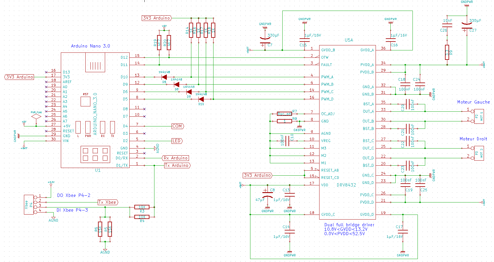
I wonder if I could get the email address of the manager / designer DRV8432DKD. I developed a prototype (CAD) using this component, but I would like someone who knows the product well take a look at my schema.

Is this possible?

Thank you in advance.

  • Romain,

    Not exactly sure what you are looking for, but would be happy to review a schematic in a PDF format.

  • Hi Ryan,

    And It's just what I wanted.

    For the record, my motor are DC 12V, 2.85A (typ.)

    I have just one question:

    In the configuration of my schematic, am I right if I say:
    PWM A controls the speed of rotation of motor 1 in one direction
    PWM B controls the speed of rotation of motor 1 in the other direction
    PWM C controls the speed of rotation of motor 2 in a direction
    PWM D controls the speed of rotation of motor 2 in the other direction

    MTE00025-03a.pdf
  • I only see one concern.  

    You have left the /RESET pins floating.  These need to be tied high for normal operation.  You can just connect them to your 3.3V supply.  

    You are correct on the control technique with one point of clarification.  You would GND the input that you are not PWM'ing.  Reverse the inputs and the DC motor will spin the other direction.  

  • Hi Ryan,

    Thanks for your answer,

    It's ok now.

    I have one more question :

    In the current configuration, I use the capacitor 1000uF but it is too large to fit in my box so I'm asking the question: is it possible to choose another capacitor since, for me, 11.5V <PvdD <13.5V.

    If yes, can you tell me the general features of the capacitor that I have to choose ?

  • General rule is to size the capacitor for 3uF per watt of output power.  So, it depends on how much current you will be driving under load in your motor.  Calculate output power for this and multiply by 3.

    You can also get away with a 25V capacitor which will reduce the size.

  • My PCB is currently in production. I look forward to test it.

    By the way can you tell me the the function performed by the resistance of 3 ohms just close to le decoupling capacitor ?

    I'll keep you posted about my test.

    Thanks.

  • The resistance of 3.3 ohms in series with a capacitor are used to shunt high frequency switching noise to GND on the supply.  This is a conducted EMI snubber.  

  • Ok, thank you.

    I've got another question :

    What will happen if I send a PWM=255 (maximum) on PWM_A and a PWM=128 on PWM_B ?

    The engine will it behave as if it receives a PWM = 128 ?

  • Hi Ryan,

    I've tested my PCB but I assume that something goes wrong. 

    I explain my problem :

    When no charge is connected, no problem, the output voltage changes between 0V and 10V

    But when I connect my DC motor, no voltage anymore...

    Enclosed you can see my schematic.