Hello TI E2E Community members,
There's currently an error with the DRV8842 (http://www.ti.com/product/DRV8842) when it is configured in this circuit.
U3, U4, and U5 are optoisolators that separate a 3.3V plane from the 12V plane that powers the H-bridge.
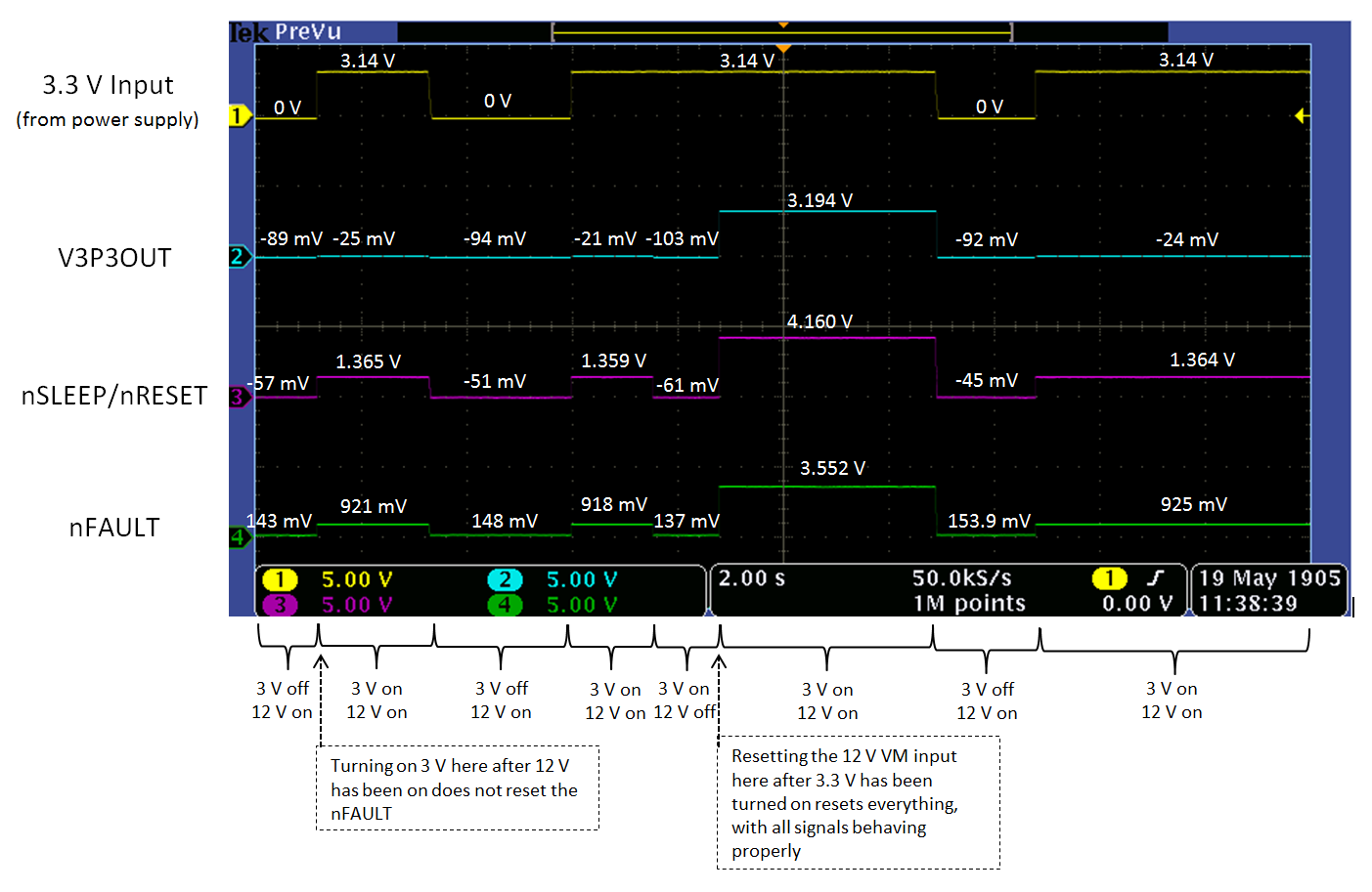
The problem is that when the 12V plane is powered on first, then subsequently the 3.3V, the pin I4 on the H-bridge draws an abnormally high amount of current.
This results in voltage levels that are too low on nSleep and nReset, so the H-bridge remains in sleep mode.
A power up in the reverse order, 3.3V then 12V, results in proper functioning of all components.
I know that I4 is the pin that is drawing an excess amount of current, because when it is tied to ground or left floating, the same voltages are seen regardless of power up order. Unfortunately, even though I am not using the current control function of the H-bridge, one current control pin (I0 to I4) must be set high to actuate the load. I tested this myself and it was confirmed by a TI employee.
Interestingly, when I implement an ideal switch instead of the optoisolator U5, either power up order works. By an ideal switch I mean removing the optoislator, powering the 12V plane, then connecting wire 4 and 3 together where the opto U5 used to be.
I have also tried using a MOSFET instead of the BJT within the optoisolator, but the same problem is seen.
To rectify the situation, I have tried tying I4 to V3P3OUT to keep it logic high that way instead, but when I do this V3P3OUT is destroyed somehow and then it outputs zero volts instead of 3.3 volts.
Any insight to this peculiar behavior of I4 would be highly appreciated.
Thank you,
~Jonathan