This thread has been locked.

If you have a related question, please click the "Ask a related question" button in the top right corner. The newly created question will be automatically linked to this question.

DRV8412: DRV8412 heating without load

Part Number: DRV8412

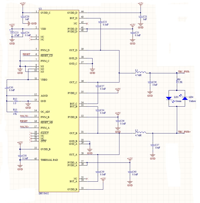
I have a designed a circuit with DRV8412 for TEC which can up to 6A at 12VDC, I have configured it to parallel full mode with LC filter connected at the output. The problem I am facing is that DRV8412 is heating a lot even without load, with several experiments I observed that when I keep the switching frequency of PWM signal fs<100kHz it start heating, with fs<10kHz the DRV8412 does not work at all, the output is 0.2VDC. What might be the problem? How can I solve this problem? 

  • Hi Haris,

    What are the input and output signals at 100kHz and 10kHz? Can you provide a scope capture of them?

    If you have a current probe, can you provide a scope capture of the current also?
  • Hello Rick,

    The input PWM signal is of 3.3V with adjustable duty cycle. The output signals are unstable DC I will share the photos, currently I am sharing the schematic of my design please have a look and give your valuable feedback.

  • Hi Haris,

    Thank you for the schematic. There could be an issue with the two output creating a shoothrough condition by connecting OUT_A/B directly with no inductor or ferrite bead.

    When operating in parallel mode, it is recommended to connect the outputs after the inductor or ferrite bead. Please refer to the description of parallel mode in section 7.4, section 9.4.5, and figure 15 of the datasheet.
  • Hello Rick,

    Thank you so much for your feedback , I think this was issue with my design but I was limited with the PCB size that's why I used two inductors.
    Can I use ferrite bead instead of inductor?what will be the difference with it?beacause for TEC, it is recommended to use inductor.
  • Hi Haris,

    You may be able to use a combination of small inductors/ferrite beads and the larger inductor to meet the design requirements.

    It is important to have a minimum of 30nH to 100nH between each output and the connection to the 4.7uH inductor. This is stated in section 9.4.5 of the datasheet.