This thread has been locked.

If you have a related question, please click the "Ask a related question" button in the top right corner. The newly created question will be automatically linked to this question.

DRV8432: DRV8432 driving TEC

Part Number: DRV8432

Hello,

I am trying to run a 24V/13A TEC with the schematic shown in Figure 17 of DRV8432's datasheet. 

As far as I understood, PWM frequency for PWM_A and PWM_B doesn't matter (I am using default 488Hz coming from analogWrite-function of Arduino Nano.).

I tried running PWM_A at 98% and PWM_B at 2% which should be enough for loading bootstrap capacitor. 

Unfortunatly, I don't get any current draw from the powersupply I use to drive PVDD. The current drawn by DRV8432 is 18.8mA at 12V measuered with my other power supply.

Should I use a faster PWM to drive the bridges? Or do you have a suggestion why it doesn't work?

Is there maybe a sample code or something I have to add in the schematic to run DRV8432 properly? 

  • Hi Tim,

    PWM frequency does matter somewhat. Please refer to section 7.3.2.1 of the datasheet. When the frequency is too low, you may need to increase the bootstrap cap. I would suggest increasing the PWM frequency first though.

    Have you monitored the outputs with no load to determine if the device is operating correctly?
    Have you looked at the FAULT and OTW pins?
  • PWM frequency is 20kHz now. 

    Yes I monitored the outputs and it seems to do nothing. 

    But I have a guess why it couldn't work. What are your recommendations for grounding on the PCB? As far as I understood the schematic in Figure 17 says it's fine to use only one ground for the whole board. Should I seperate the ground of GVVD and PVDD? 

    The FAULT and OTW pins were logic HIGH, so everything is fine.

  • Hi Tim,

    The device should have one ground for both GVDD/VDD and PVDD.

    What is the state of RESET_AB and RESET_CD? In parallel bridge mode, RESET_AB and RESET_CD control the bridge. Both must be a logic high for the bridge to operate. This is described in section 7.4 of the datasheet.

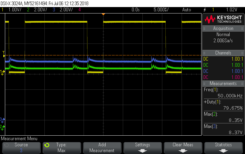
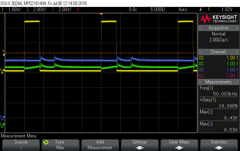
    Can you provide scope captures of
    PWM_A and PWM_B inputs
    PWM_A input and OUT_A/B outputs
    PWM_B input and OUT_C/D outputs?

    Please zoom in to observe a full PWM period. Of interest is whether the outputs are attempting to drive.
  • The state of RESET_AB and RESET_CD is both logic high. 

    Here is PWM_A (80%, yellow) and PWM_B (20%, green). Every signal is made with 3.3V logic.

    PWM_A (yellow) input and OUT_A(green)/B(blue) output:

    PWM_B(yellow) input and OUT_C(green)/D(blue) output:

    Interestingly, I measuered PWM_B input and OUT_C/D output with no PVDD voltage and there was almost the same result as with PVDD voltage on:

  • Hi Tim,

    The scope captures show the device is not operating as expected. The reason is unclear.

    Please check the voltages at the BST_A/B/C/D and VREG capacitors. BST_A/B/C/D should be approximately 10V and VREG should be ~3.3V when VDD/GVDD_x is 12V and the PWM_A and PWM_B inputs are low.

    This will confirm the internal logic is awake and the connections at the VDD/GVDD_x pins are correct.

    Also please check the connections at the M3, M2, M1, RESET_A, and RESET_B pins in case there is a broken connection.

    If everything checks out, do you have a second board to try?
  • BST_A/B/C/D are about 12V and VREG is 3.3V with PWM_A/B low. The supply voltage for GVDD_x is 12V. There was a broken connection at VREG and BST_D but it didn't solved the problem.

    I am still getting no current draw at PVDD. 

    Unfortunately not. I had another board with one GND for PVDD and VDD/GVDD but it broke. Right now I am testing on a Board with two seperated grounds. Is one ground for correct operation of the DRV8432 required?

  • Hi Tim,

    If there was a broken connection at VREG, some of the internal logic could have been damaged. Without the VREG capacitor there could have been spikes on the internal logic that caused damage to the device.

    In addition to no current draw, I am assuming the outputs are not toggling. Is that correct?

    You may have to replace the DRV8432 to confirm there was no damage.

    As long as the ground remain close together (within +/-0.3V) there should be no problem. We recommend connecting all the ground together with the exception of AGND. AGND should be connected to the other grounds with a one Ohm resistor.
  • Thank you for your time and help! 

    Replacing the DRV8432 was the right hint.