This thread has been locked.

If you have a related question, please click the "Ask a related question" button in the top right corner. The newly created question will be automatically linked to this question.

DRV8305: Charge Pump Supply Debugging

Part Number: DRV8305

Hey Folks, 

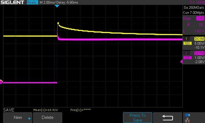
I'm struggling with debugging the charge pump on the 8305 on a custom board. My layout has been tested and works for a little while, but stops working after a few tests (Lab 2c bringup). The behavior after the fault is that the charge pump VCPH pin goes high and then decays as if it stopped running. Are there any debug tips to fix this particular behavior? 

Chad

  • Hi Chad,

    Could you perform a SPI read of registers 0x1, 0x2, 0x3, and 0x4 so we can find out what kind of fault the device is seeing?

    Thanks,
    Garrett
  • Thanks Garrett, 
    I have VCPH_UVLO2 in register 3 and the corresponding fault in register 1, combined with the global fault bit. 

    I also found that the charge pump capacitor measures 250 ohm across the capacitor in both directions (C_VCPH on docs). I think this implies and issue with either my layout or with the DRV8305 chip. In debugging today, I do believe I blew out the chip so I'll be building up another board today for testing and plan to update based on the initial parameters and track degradation while bringing up that board. 

    (edit)

    New out of the box, the resistance is 50k+ on that same measurement, so it implies that something degrades in a few minutes of running with the bringup procedure. This same system works correctly with the DRV8305-Q1EVM board without any issues, so it's a matter of figuring out what I am doing wrong compared to that system. 

    Chad

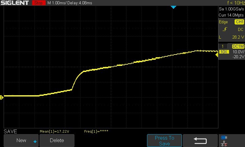
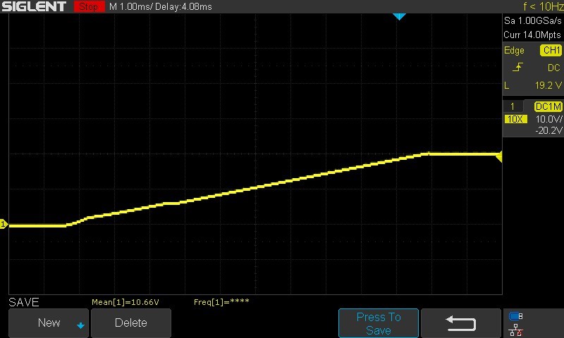
  • Adding more information on failure: I have scope snapshots comparing the Q1EVM board with the custom board. The Q1EVM has a distinct turn on point and goes to full Vb + 10v, while the custom board has a gradual slope and only goes to Vb.

    DRV8305-Q1EVM board trace for VCPH to GND

    Broken board trace from VCPH to GND

  • Hi Chad,

    That certainly suggests a damaged part to me. VCPH is the overdrive supply for the high-side FETs, so it should normally regulate to around VBAT + 10. Would you be willing to share your schematic, or at least the portions related to VCPH, CP1L/H, CP2L/H, and VCP_LSD?

    Thanks,
    Garrett