


Part Number: DRV8323
Other Parts Discussed in Thread: TMS320F28069,
Tool/software: TI C/C++ Compiler
Hi,
I am working with a SPI connection between the TMS320F28069 (master) and the DRV8323 (slave).
SPI sample rate: 4.5Mhz
nFAULT and SDO external pullup resistances: 4.7kHz.
ENABLE: 3.3V
Here is how i setup and use the SPI connection:
GPIO's are initialized:
void InitSpiaGpio()
{
   EALLOW;

    GpioCtrlRegs.GPAPUD.bit.GPIO16 = 2;   // Enable pull-up on GPIO16 (SPISIMOA)
    GpioCtrlRegs.GPAPUD.bit.GPIO17 = 0;   // Enable pull-up on GPIO17 (SPISOMIA)
    GpioCtrlRegs.GPAPUD.bit.GPIO18 = 0;   // Enable pull-up on GPIO18 (SPICLKA)
    //GpioCtrlRegs.GPAPUD.bit.GPIO19 = 0;   // Enable pull-up on GPIO19 (SPISTEA)

    GpioCtrlRegs.GPAQSEL2.bit.GPIO16 = 3; // Asynch input GPIO16 (SPISIMOA)
    GpioCtrlRegs.GPAQSEL2.bit.GPIO17 = 3; // Asynch input GPIO17 (SPISOMIA)
    GpioCtrlRegs.GPAQSEL2.bit.GPIO18 = 3; // Asynch input GPIO18 (SPICLKA)
    GpioCtrlRegs.GPAQSEL2.bit.GPIO19 = 3; // Asynch input GPIO19 (SPISTEA)

    GpioCtrlRegs.GPAMUX2.bit.GPIO16 = 1; // Configure GPIO16 as SPISIMOA
    GpioCtrlRegs.GPAMUX2.bit.GPIO17 = 1; // Configure GPIO17 as SPISOMIA
    GpioCtrlRegs.GPAMUX2.bit.GPIO18 = 1; // Configure GPIO18 as SPICLKA
    GpioCtrlRegs.GPAMUX2.bit.GPIO19 = 1; // Configure GPIO19 as SPISTEA
    //GpioCtrlRegs.GPADIR.bit.GPIO19 = 1;   // All outputs
    //GpioDataRegs.GPADAT.bit.GPIO19 = 0;

    EDIS;
}
The SPI connection is configued:
void spi_init()
{
    SpiaRegs.SPICCR.all =0x000F;                 // Reset on, rising edge, 16-bit char bits
    SpiaRegs.SPICCR.bit.SPILBK=0;
    SpiaRegs.SPICTL.all =0x0006;                 // Enable master mode, normal phase,
                                                 // enable talk, and SPI int disabled.
    SpiaRegs.SPICTL.bit.TALK = 1;
    SpiaRegs.SPIBRR =0x0004;
    SpiaRegs.SPICCR.all =0x008F;                 // Relinquish SPI from Reset
    SpiaRegs.SPICCR.bit.CLKPOLARITY=0;
    SpiaRegs.SPIPRI.bit.FREE = 1;                // Set so breakpoints don't disturb xmission
}
SPI FIFO is initialized:
void spi_fifo_init()
{
// Initialize SPI FIFO registers
    SpiaRegs.SPIFFTX.all=0xE040;
    SpiaRegs.SPIFFRX.all=0x2044;
    SpiaRegs.SPIFFCT.all=0x0;
}
I'm using the below function to read from SPI
Uint16 DRV8323_readSpi(Uint8 regAdr)
{
    Uint16 controlword = 0x8000 | (regAdr & 0x7) << 11; //MSbit =1 for read, address is 3 bits (MSbit is always 0), data is 11 bits
    spi_xmit(controlword);
    Uint16 temp = spi_read();
    return temp;
}
In the main function i have tried calling DRV8323_readSpi(0x9800) and DRV8323_readSpi(0xA800) which should correspond with reading from "Gate Drive HS register" and "Driver Control register", respectively. However, both commands results in the SDO being purely high. It never returns any 0 at all. Scope pictures from the test (reading from "Driver Control register"):
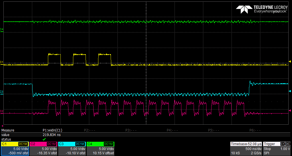
Green: SDO
Yellow: SDI
Blue: nSCS
Pink: SCLK
It seems like i comply with the SPI timing requirements, stated in the DRV8323 datasheet. Can you please help me figure out the problem?
Thanks
