This thread has been locked.

If you have a related question, please click the "Ask a related question" button in the top right corner. The newly created question will be automatically linked to this question.

DRV8832: DRV8832 Rsense issue

Part Number: DRV8832
Other Parts Discussed in Thread: DRV8833, DRV8833C

our customer one project need control gate to open or close on some occasion. Recently, encounter a problem in utilizing DRV8832 chip-set to control gate. The detailed information is as follows.

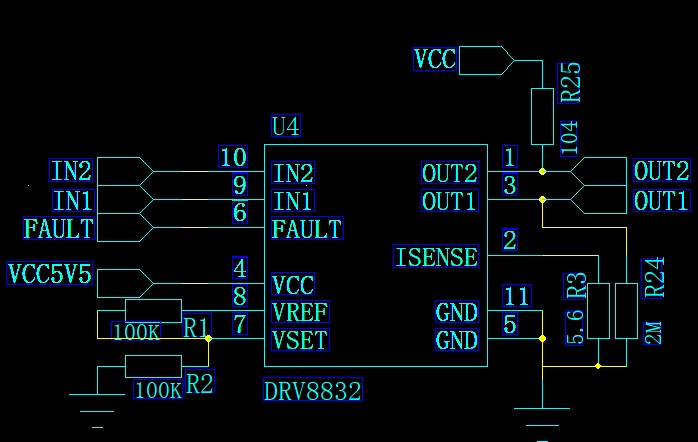
Background: Because of small stall current based on the adopted gate, 100mA or so is expected. According to specification of DRV832, the voltage of “Vset” is designed to half of “Vref”. Therefore, the voltage of output to gate is designed to 2.5V or so. The voltage of “Vcc” is provided by battery, the value spans the range between 6.0v and 4.0v.  In order to achieve feedback of “Fault” pin, “Rsense” increases to 5.6 ohm(Ω) with “Vcc” of 6.0v. That seems work well.

Problem: Further verify closing or opening the gate with lower voltage of “Vcc”, found out that no feedback on “Fault” pin after “Vcc” decrease to 5.0V or less, and mistake this as an exception in closing or opening gate.

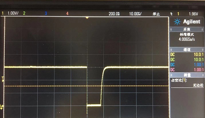
Experiment 1: The motor internal resistance of gate is 25 ohm(Ω) . Based on the hardware configure of “Vcc: 6.0v” mentioned before, the voltage of output is 2.5v or so as expected with zero-load, meanwhile, outout voltage is 0.8v that is unexpected with the gate load. If replacing with “Rsense” of 1 ohm(Ω), the voltage of output seems constant, 2.5v output is expected , regardless of zero load or gate load. That’s weird.  Why? (1)

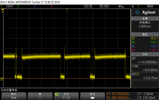
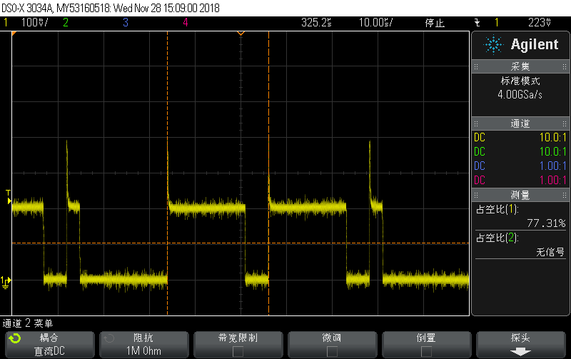
Experiment 2: Based on “Rsense” of 5.6 ohm(Ω), while altering voltage of “Vcc”, the voltage of output seems not constant with gate load. Under the “Vcc” of 5.0v or less, No feedback on “Fault” pin. Why? (2)

Problem: “The resistor used to set the current limit must be less than 1Ω.” , which is cited from the specification of DRV8832. May I have the cause of the requirement? (3)

Solution: Any solution related to the application based on DRV8832? (4)


Looking forward to your feedback related to the four questions Thanks a lots.

  • Hi Lina,

    How are the inputs IN1 and IN2 set during the experiments?

    Can you provide scope captures of Experiments 1 and 2?
    Please provide zoomed in and out captures of OUT1, OUT2, ISEN, and FAULTn voltages.
    Please provide these images during motor start, normal operation, and at stall.
  • Hi Rick,

    First of all, thanks for your support. I’m a customer encountering the problem described in current issue.

    This issue occurs easier in closing gate which has been closed before. As expected, “Fault” pin should feedback to indicate end of close. But no feedback on “Fault” pin with lower voltage and 5.6ohm Rsense.

        As you required, some scope images are provided here.


    1.VCC:6.0v (Vbat), Rsense: 1ohm, IN1: High, IN2: Low, Out1: Yellow, Out2: Green, Load: Gate

    Voltage of output: 5*(100-44.273)/100 = 2.78V (Close to 2.5V )

    2. VCC:6.0v (Vbat), Rsense: 1ohm, IN1: High, IN2: Low, Out1: Yellow, Out2: Green, Load: NULL

    Voltage of output: 5.4*(100-52.340)/100 = 2.57V (Close to 2.5V )

    2.VCC:6.0v (Vbat), Rsense: 5.6ohm, IN1: High, IN2: Low, Out1: Yellow, Out2: Green, Load: Gate

    Voltage of output: 5.2*(100-81.44)/100 = 0.96V (deviate from 2.5V, unexpected)

    3. VCC:6.0v (Vbat), Rsense: 5.6ohm, IN1: High, IN2: Low, Out1: Yellow, Out2: Green, Load: NULL

    Voltage of output: 5.1*(100-49.21)/100 = 2.59V (Close to 2.5V)

    4. VCC:4.5v (Vbat), Rsense: 1ohm, IN1: High, IN2: Low, Out1: Yellow, Out2: Green, Load: Gate

    Voltage of output: 3*(100-8.69)/100 = 2.73V (Close to 2.5V)

    5. VCC:4.5v (Vbat), Rsense: 1ohm, IN1: High, IN2: Low, Out1: Yellow, Out2: Green, Load: NULL

    Voltage of output: 4*(100-34.52)/100 = 2.61V (Close to 2.5V)

    6. VCC:4.5v (Vbat), Rsense: 5.6ohm, IN1: High, IN2: Low, Out1: Yellow, Out2: Green, Load: Gate

    Voltage of output: 3.8*(100-75.44)/100 = 0.93V (deviate from 2.5V, unexpected)

    7. VCC:4.5v (Vbat), Rsense: 5.6ohm, IN1: High, IN2: Low, Out1: Yellow, Out2: Green, Load: NULL

    Voltage of output: 3.9*(100-34.02)/100 = 2.57V (Close to 2.5V)

    Summary: Voltage of output is unexpected as design with Rsense 5.6ohm and load of gate, regardless of Vcc.


    The following images show the process of closing gate, the fist image show that output wave(Vcc: 6.0v, Out1: Yellow, Out2: Green). The second image show the voltage of Rsense(Green) and feedback of “Fault” pin (Yellow).


    Because of limit, for now, we provide those scope images here. Look forward to your supports. Thanks.


    Best regards,

    Qingfeng Yuan

  • dear sir,

    DRV8832's Spec is show the Rsense should limit to 1OHM, I want to know if this Rsense bigger than 1ohm, what's happen phenomenon for it? 

    why Rsense should limit 1ohm, could you help to share some theory basis for it, I also have look DRV8833, But that part haven't mentioned this limit for Rsense. 

    if I need set the over current limit on the 70mA, could you have more suitable solution? or do you have any other comment, thanks.

  • Hi Rick,

      The following diagram is a schematic related to DRV8832, please help correct the problem based on 70ma - 100ma current limit. Until now, the problem, that is, no feedback on Fault pin except for short low level during closing the closed gate with lower voltage, such as 4.0v(Vcc), still haunt us.

    The following wave capture of "Fault" pin show that  the period of low level is very short, less than 10us. And then no other feedback present in the subsequent phase.

    Looking forwart to your help, thanks a lots!!

    Best regards,

    Qingfeng, Yuan

  • Hi Qingfeng Yuan,

    Thank you for the additional information.

    If the sense resistor is too high, the PWM duty cycle can be limited. This may be occurring when using a 5.6Ohm resistor.
    If the sense resistor is too low, the stall detection may not operate. This may be occurring when using a 1Ohm resistor.

    The Risen resistor is primarily used to detect a stall condition. The DRV8832 limits the current during startup by slowly increasing the PWM duty cycle. The Risen resistor should be set to ~75 to 80% of the stall current. Setting the value this high will allow the motor to start, and will create enough voltage to detect a stall condition.

    Assuming a 25Ohm motor resistor and Vcc = 4V , stall current is 160mA. With a 20% variation of the comparator, it is recommended to set the Risen resistor to 2Ohms. Using 2Ohm will create up to 320mV when the motor is stalled. This is above the 240mV maximum trip point.

    A rough equation for selecting the Risen resistor is:

    Risen = 320mV/(VCCmin/(Rmotor_max + Rdson_HS_max + Rdson_LS_max))

    The 320mV is 80mV above the 240mV max trip point. This should provide enough margin to trip the comparator.

    FYI:

    1) The RIsen resistor can be increased above the 1Ohm. This will be modified in a future datasheet update.
    2) The stall detection operates by counting consecutive trips of the Ilimit comparator. There should be ~12288 consecutive trips of the Ilimit comparator (275ms/22.47us). If a trip does not occur, the count is reset to zero and begins again.
  • Hi Rick,
    Thanks for your useful information. It's very clear. But, something is confusing, that is, stall current is caculated based on Vcc, rather than Vout, Why? Based on current project, Vout is designed to 2.5v or so based on the value of Vset.

    Best regards,
    Qingfeng, Yuan
  • Hi Qingfeng, Yuan

    The average Vout voltage should be ~2.5V when the motor is operating properly. When the motor is stalled, the average Vout voltage could be different depending on the current rise due to lack of back-EMF and the Risen value.

    When the motor is stalled or starting, the current can be as high VCCmax/Rmotor_min unless it is limited by the Risen resistor. At startup, the Risen should be set to allow enough current to start the motor.

    Using a 5.6Ohm resistor limits the current to 28mA to 42mA (typically 35mA). That is why you saw the lower average voltage.
    Using a 1Ohm resistor limits the current to 160mA to 240mA (typically 200mA). That is why you did not see the nFAULT indicating a stall.
    Using a 2Ohm resistor suggested limits the current to 80mA to 120mA (typically 100mA). This should be sufficient to allow startup and detect a stall.

    The suggest resistor value can be adjusted to your needs. You can measure the ISEN voltage to determine the current needed during startup and stall. Then you can adjust the Risen resistor.

    Please consider the variations of motor resistance, device Rdson, and the comparator when adjusting the resistor.
  • Hi Rick,
    Thanks for your detailed information. I can get the theory related to DRV8832.

    Appreciate your reminding.

    Best regards,
    Qingfeng, Yuan
  • Hi Rich,

       According to your suggestion and theory you provided, Risens is adjusted to 2.2ohm. The voltage of Vout is expected as design: 2.6v, which is closing to 2.5v.  That's reasonable for now. But, no feedback on "Fault" pin still exists. The voltage of Risens is captured as follows:

    Even you has introduced  how to evaluate limit current, but there are some confusion because of wave of Risens's voltage, rather than a constant voltage. These wave doesn't trigger "Fault" event. What wave can trigger "Fault" event??

    Sorry for trouble again

    Best regards,

    Qingfeng, Yuan

  • Hi Qingfeng, Yuan

    Is the scope capture provided during a stall condition?

    Assuming this is a stall condition, the voltage at the sense resistor is ~200mV. The current is ~90mA. The voltage is not enough to consistently trip the isense comparator.

    Please increase the sense resistor to 3 Ohms and try again. That should provide ~270mV at the sense pin.

    Below I have added a clarification to the stall detection:

    The stall detection operates by counting consecutive trips of the Ilimit comparator during a PWM cycle. There should be ~12288 consecutive trips of the Ilimit comparator (275ms/22.47us). If a trip does not occur during a PWM cycle, the count is reset to zero and begins again.

    In the image above you can see several times where the isense voltage remains at 200mV for more than 22.5us. This will reset the counter.

  • Hi Rick,

     The scope capture is captured during a stall condition.

      “Assuming this is a stall condition, the voltage at the sense resistor is ~200mV. The current is ~90mA. The voltage is not enough to consistently trip the isense comparator”, from which deduce that the voltage of Risense must be more than 200mV, or not?

      During a stall condition, the high level of PWM cycle for the voltage of Risense should take into account, and the low level should ignore, rather than the average voltage of PWM cycle, to be evaluated for Vilimit.  What I understand is right, or not??

      Additionally, according to discussion in last post, what I understand is that if not reach Vilimit, DRV8832 should increase the voltage of Vout until to Vcc. Therefore, the voltage of Risense may be a constant vale while Vout is equal to Vcc.  Is that true?  Today, do experiments, and monitor the voltage of Vout. Vout is not equal to Vcc during a stall condition and not trigger “fault” report. Vouct seems equal ~2.6v that is designed with Vset. Could you help clarify?

      Is there a relationship between Vset and Vilimit?

      Thanks again!

    Best regards,

    Qingfeng,Yuan

  • Hi Qingfeng, Yuan

     “Assuming this is a stall condition, the voltage at the sense resistor is ~200mV. The current is ~90mA. The voltage is not enough to consistently trip the isense comparator”, from which deduce that the voltage of Risense must be more than 200mV, or not?

    The voltage of Risense must be more than 240mV to ensure proper detection. This will account for the +/-20% variation of the Vilim comparator.

     During a stall condition, the high level of PWM cycle for the voltage of Risense should take into account, and the low level should ignore, rather than the average voltage of PWM cycle, to be evaluated for Vilimit.  What I understand is right, or not??

    During a stall, there is no back-EMF. This can cause the current to increase and exceed the 240mV Isense trip voltage.

     Additionally, according to discussion in last post, what I understand is that if not reach Vilimit, DRV8832 should increase the voltage of Vout until to Vcc. Therefore, the voltage of Risense may be a constant vale while Vout is equal to Vcc.  Is that true?  Today, do experiments, and monitor the voltage of Vout. Vout is not equal to Vcc during a stall condition and not trigger “fault” report. Vouct seems equal ~2.6v that is designed with Vset. Could you help clarify?

    During each PWM cycle, the voltage across the motor is VCC for the drive portion. The DRV8832 adjusts the duty cycle to create an average voltage specified by the VSET pin *4 (2.5V in your application). When the motor stalls, the current during each pwm drive cycle increases due to the lack of back-EMF.

     Is there a relationship between Vset and Vilimit?

    If the sense resistor is set properly, there should be no relationship.
    If the sense resistor used is set too high, Vset may not be reached. The device may PWM at a lower average voltage.

    Overall, the sense resistor must be:
    1) large enough to detect a stall. This means the current in the motor during a stall must create at least 240mV at the Isense pin
    2) small enough to allow the motor to start and reach Vset.

    Most motors can start within the 275ms stall detection window. I think you were close to working at 2.2Ohm. 3Ohms should meet your needs. 

  • Hi Rick,
    During a stall condition, if the voltage of Risense is still presented with PWM circle, need take the inductive impedance of motor into account. Not only the resistance of motor. Do you think so?
    If using 3ohm for Risense, Vout cannot reach designed voltage, is that OK??

    Best regards,
    Qingfeng, Yuan
  • Hi Qingfeng, Yuan,

    You are correct. The inductive impedance needs to be taken into account also.

    The voltage across the motor should still reach the designated voltage. The integrator shown in Figure 7 is measuring the voltage across the motor. The sense resistor is not part of the voltage integrator.
  • Hi Rich,

      After replacing with Risense of 3ohm, "Fault" report cannot be tirggered as expected yet. Monitor the voltage of Risense during a stall condition and capture the scope waveform as follows:

    It seems always 200mv or so, same as 2.2ohm. It's weird.  The problem happens to close the gate which has been in cloed state. When start to close gate, deduce from problem that DRV8832 want to increase PWM cycle to  the expected voltage of Vout, but because of current limit of Risense, stop increasing PWM cycle to meet 200mv on Risense, and limit Vout into 1.7v or so. If increasing the Risense to 3.6ohm, the volgate of Risense is almost simlar. 

    Look forward to another feasible suggesion, thanks!

    Best regards,

    Qingfeng, Yuan

  • Hi Qingfeng, Yuan

    The Vilim trip point on an single IC should be relatively constant. For the device you are testing, the Vilim trip point is approximately 200mV.

    Each time the voltage reaches ~200mV, the device will enter current regulation.

    Raising the sense resistor caused Vilim to be consistently triggered. When Vilim is consistently triggered, there is no need to increase the sense resistor for the device being tested. There may be a need to increase the resistor to account for the +/- 20% variation of the Vilim circuit.

    The scope capture shown should create a stall condition. It appears there is no drive pulse longer that the PWM period of ~22us.

    Please look for a Isense voltage pulse of >22us during the stall. Your scope should be able to trigger on the long pulse or record the longest frequency/pulse width. A pulse of >22us would reset the counter and prevent a stall from being detected.
  • Hi Rick,

       After several experiments with different values of Risense, the voltage of Risense during a stall condition is almost simlar, and the voltage of Vout decreases proportionally. Therefore, get the rule that DRV8832 is try to regulate current based on Vilimit during the starting phase.  This process is trying  its best  to start close or open operation and avoid mistrigger "Fault" report.

      Regarding the current problem, try to close the closed gate and always locate in the starting phase. Therefore, no "Fault" report during the real stall condition. Maybe lack of the process of "start, operation, stall", lack of the process of back-EMF, DRV8832 cannot detect the stall condition and always maintain current to keep Vilimit.

      Based on the deduction above, the driver of motor try to simulate the process of "start, operation, stall" and solve the problem for now.

      Could you detail something based on my deduction? Is it right??

      Thanks for your kind, patient supports!

    Best regards,

    Qingfeng, Yuan

  • Hi Qingfeng, Yuan

    The stall detection circuit is probably resetting periodically, at least once within each 275ms count. I have seen this in the past, and there is typically no good method to fix this. You may be able to monitor measure the duty cycle, after a specified time using a timer/counter. There should be a difference between running and stall.

    There are other options, like the DRV8833C. This device cannot set the output duty cycle, but can be used to detect a stall. An example of how this would be done can be found here:   

    During startup the device will regulate current. During normal operation, the device will provide 100% duty cycle so the motor voltage will be higher than 2.5V. As the motor stalls, the current will again be regulated. The outputs will begin PWM'ing and monitoring the outputs can detect this.

  • Hi Rick,

      Thanks for your support!  I got a lots through this discussion, and then can solve the problem. 

      Your information is very important for us to understand. Appreciate your helps.

    Best regards,

    Qingfeng,Yuan