This thread has been locked.

If you have a related question, please click the "Ask a related question" button in the top right corner. The newly created question will be automatically linked to this question.

DRV8305: Driver chip overheating abnormally

Part Number: DRV8305
Other Parts Discussed in Thread: DRV8323, LAUNCHXL-F28069M, MOTORWARE

Hi, 

I am an electrical engineering student designing a 3 phase bldc motor driver circuit mostly based off the DRV8305 typical application data and EVM. I have manufactured a PCB and done the standard electrical continuity tests. My design is mostly based off the typical application circuit and DRV8305EVM with some additional features that are not relevant to this discussion.

I find that the DRV8305 becomes abnormally when it is connected even in an idle state. 

Once operating the IC begins to heat excessively to a point where the package is too hot to touch after running the code for barely one second. The mosfets stage stay cool however. 

I have no idea how to troubleshoot this problem and my equipment is somewhat limited. 

I've read that the IDRIVE settings, TDRIVE settings and Deadtime can be used to adjust the FETs gate current so to prevent overheating but I am still confused of how to chose the IDRIVE and Dead time settings. I read that the Tdrive settings should be about 2 times the rise time of the MOSFETs. 

In my case 2x 91ns would be 182ns which is shorter than any of the settings available. So I would chose the lowest setting of 220ns. 

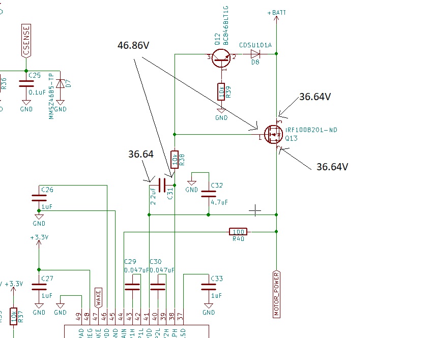
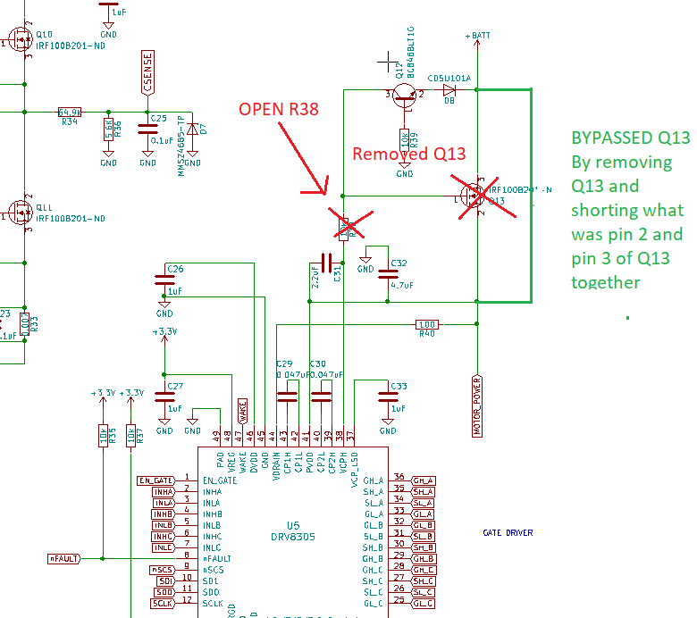
I am attaching my schematic here. 

Any help would be appreciated ! :) 

PCB_DRIVER.pdf

  • Steven,

    You can back calculate the needed iDrive from section 8.2.2.2 of the DRV8305 datasheet.

    The DRV8305 is an older device, our newer DRV8323 has a better explanation of how to set iDrive:

    Section 9.2.1.2.2 of www.ti.com/.../drv8320r.pdf

    I don't see any glaring errors on your schematic.

    What lab equipment do you have available?

    It looks like you might be using 6x PWM, have you checked to make sure those input signals are valid?

    Regards,

    -Adam
  • Hi Adam, thanks for your reply. I found a small issue in my circuit not much of an issue itself but I had 100x the capacitance required across the current sensing resistors. I've changed them to 1nf.

    We are indeed using 6pwm and from the datasheet I did calculate the required IDRIVE and TDRIVE settings. Unfortunately this did not resolve the issue.

    Update: the chip burned out today a hole has popped through the drv8305 and the R40 resistance has been burned through as well. I want to point out that I am using the Drv8305N chip and an external 3.3V supply as vref rather than using the chip's built in LDO. Also I have connected my driver with the Texas instrument launchpad without adjusting the jumper settings to disable USB power. I am curious if this might have played a role in the chip burning our. I will replace it and asses the situation. I will also try to measure the pwm signals
  • Steven,

    If you are using 5V logic and 3.3V as the reference voltage then something is likely to get damaged.

    The mismatch will probably cause excess heat also.

    Regards,

    -Adam
  • Hi Adam, 

    Thanks again for your response. And please forgive me if what I am asking seems obvious or off topic. 

    The circuit I have shown is connected with the LAUNCHXL-F28069M. I supply 3.3V from the onboard dc-dc converter both to the DRV8305 Vref pin and to the MCU though the pin headers.

    On the MCU we intended to use 3.3V logic however by mistake the following jumper settings were used : (JP1 - JP5 : ON ) , JP6 : OFF. Furthermore, the LAUNCHXL was powered from a computer via USB simultaneously while my ciircuit was supplying it 3.3V from my onboard regulators.

    I believe this confirms the error> see attachment extracted from LAUNCHXL-F28069M datasheet.

    I am not 100% sure of exactly what would happen using the wrong jumper settings but I think it is possible that this has been the source of my issues. I am looking forward to putting in a new chip next week and trying it out.

    Do you think that is the reason why it overheated ? 

    Sorry again I am new to both the TI forum and TI products. 

    Regards,

    Steven

    LAUNCHXL-F28069M
  • Steven,

    Yes this is likely your issue. Please try the new IC and let us know.

    Regards,

    -Adam
  • Hi Adam, 

    I've populated a new IC into my board and tested it out once more. I've removed JP1, JP2, JP3 from the launchpad. 

    Chip still gets super hot as soon as it runs (like within less than a second). I am completely out of ideas. Any recommendations ?

    Regards ,

    Steven 

  • Steven,

    When you say "runs" do you mean the inputs are switching? If they are, what frequency?

    I'm concerned that VREG is powered by 3.3V as soon as the BAT+ is connected but VDRAIN and PVDD are still coming up, can you check the timing on these three supplies at the DRV pins?

    Can you remove R40 and see if the device still gets hot?

    Regards,

    -Adam

  • Hi Adam, 

    Thanks again for your response.

    We are currently running sample code provided in the motorware package ->  instaspin_foc solutions lab2_a. By that I mean that once connected to the board with system enabled I can run the code for about 1 second before which the chip becomes to hot to touch. At that point I immediately cut the power supply to prevent damage to the chip. 

    I've attached a screen shot of the voltage waveform available at the gate of the high side mosfet Q2 (pin1) during one of those short 1 second experiments.

    .

    We can see that it is correctly reaching a value of PVDD + 10 V and it seems to be running at about 45 kHz  ( off topic here... I would like to change the frequency but I believe this is not possible until lab 3 or 4 which require successful identification of the motor parameters in lab_2a. So from my understanding we are a bit stuck with these settings software wise until we can fix the heat issues.. ) 

    Regarding Q13 you are right it is intended for reverse polarity protection. I've attached a screen shot of the DRV8305 guidelines for reverse polarity protection to this comment as well. I've been trying to understand what I've done wrong comparing the both of them but I don't see any differences. I've also attached some voltage readings that I was able to take off my board in a steady state with the board powered from a 36V supply and without running any code.

    My understanding is that Q13 is conducting under these conditions shown below.


    It might be difficult for me to determine any possible timing issues between the 3.3V Vref , VDRAIN and PVDD as I am not sure exactly how to do so. However if you could clarify for me what you mean by checking the timing on these pins I can of course do everything within my abilities.

    Also, by removing R40 do you mean just disconnect it and leave Vdrain floating ?

    Also, I don't mind removing the reverse polarity protection scheme altogether for now if you think that could solve the issue!! :) 

    Thank you so much again for your help. Please let me know what action you think is best. 

    Steven 

  • Steven,

    I would start bypassing the reverse polarity protection and Q13 and check if normal operation can happen without overheating.

    Regards,

    -Adam
  • Hi Adam, 

    Thanks again for your recommendations I truly appreciate the help. 


    I've removed the reverse polarity protection scheme as in the image attached below. It still heats up super fast as soon as system enable turns on. 

    I am completely out of ideas. Do you have any recommendations ? 

    Steven 

  • Could this have anything to do with the LDO being disabled ? I've mentioned this before I believe but I am using the DRV8305N model which is supposed to have the LDO disabled and I am supplying 3.3v to pin 48 from an external dc dc converter. The enable system command in Motorware is supposted to set EN_GATE pin high which is supposed to turn on the LDO inside the chip. Being how I have the DRV8305N version could this be a source of problems ?
  • Steven,

    Please experiment with turning off the 3.3V supply or removing the enable command and see what helps.

    Regards,

    -Adam
  • Hi Steven,

    I have seen no update on this thread, did your issue get resolved?

    I will mark this thread as closed but please post if you need further assistance.

    Regards,
    Michael
  • Hi Adam, 

    So I'm still working on this, the issue is not resolved. I am populating a new PCB and had to wait on new parts. I'm changing to the DRV83053 instead of the DRV8305N and cutting a few traces so to use the internal LDO as reference 3.3V and power my MCU of a separate circuit. 

    I will update you on the process as soon as I manage to get it done . 


  • Hi Micheal the issue is not resolved I am working on a new PCB and will continue testing this week. Thanks
  • I am making a new PCB and experimenting with the supply. I will keep you updated by the end of the week.
  • Steven,

    I need to close this thread due to inactivity, please use the "ask a related question" button when you have more for us.

    Regards,

    -Adam
  • I have new board with the  same issues. I've checked the SPI registers and the only flags being raised are the temperature ones. 

    Is there any ways to decrease the clock speed on this ? I know that SCLK receives data from our launchpad but there appears to be no possible way to change the clock speed...

    Thanks

  • I resolved the issue by putting a huge heat sink on top of the IC. Motors run smoothly now. I think the issue had to do with the copper being too small to dissipate enough heat.