This thread has been locked.

If you have a related question, please click the "Ask a related question" button in the top right corner. The newly created question will be automatically linked to this question.

DRV8701: Intermediate spikes on SO & SNSOUT lines

Part Number: DRV8701

Hector, following up on the thread in https://e2e.ti.com/support/motor-drivers/f/38/p/791764/2947255 where we were searching for an answer to some suspect signal spikes, here are the answers to your questions:


1. Is the IC utilized DRV8701E or DRV8701P?

DRV8701E


2. Is the driver configured in half bridge or full bridge mode?

Full bridge


3. What is the IDRIVE setting? What FETs are being utilized?

IDRIVE setting is 150 source, 300 sink (68k between IDRIVE and AVDD).
Using SI7938DP FET.


4. Has the datasheet section 8.2.1.2 Detailed Design Procedure been followed when selecting the IDRIVE setting, FETs, and PWM frequency?

Confirmed. IDRIVE is 65 mA @ 100 ns, 216 mA @ 300 ns; Qg < 250 nC (Qg = between 21 & 43 nC).


5. Have there been any trials utilizing a different motor/load? Isolating the variables that can cause a current spike and removing them will help to determine where the issue comes from.

Not to date.

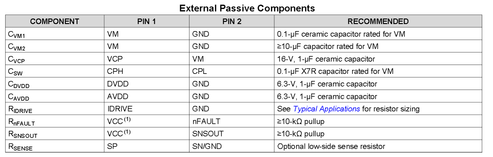
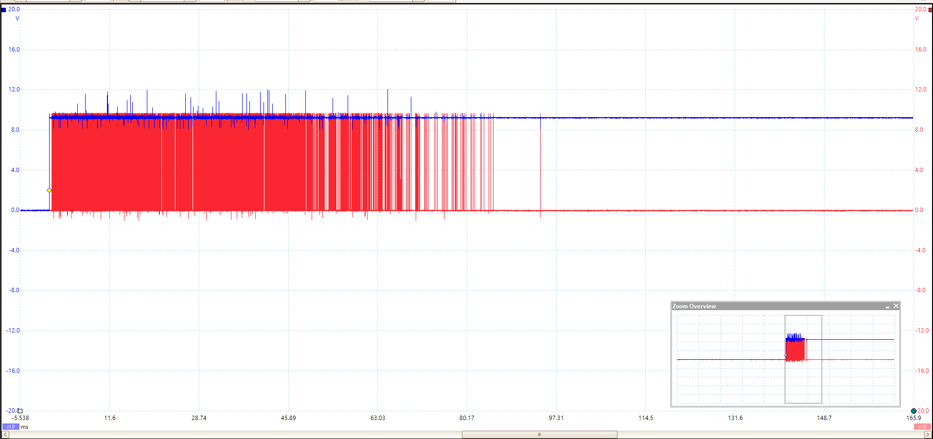
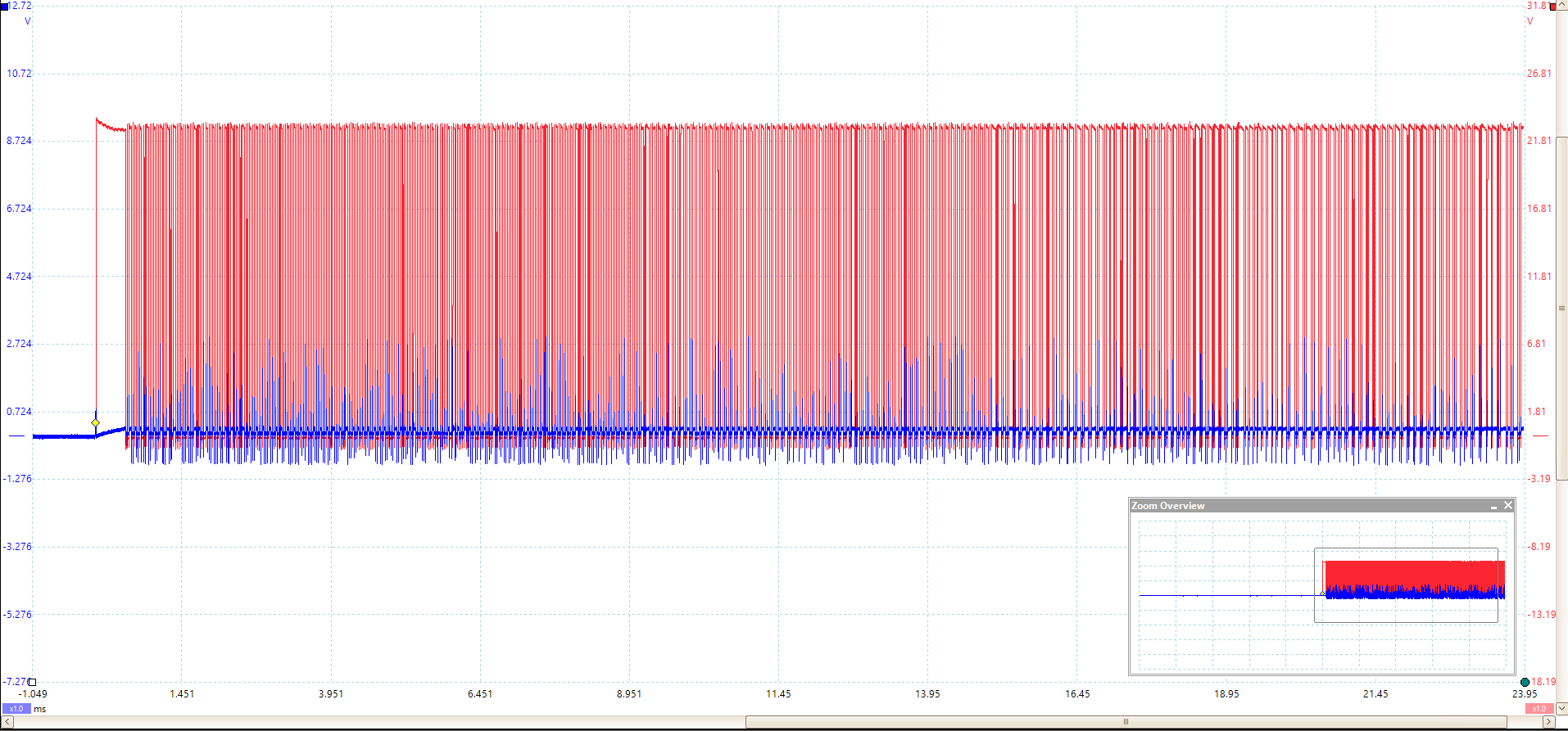
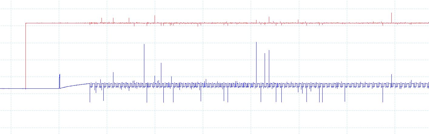
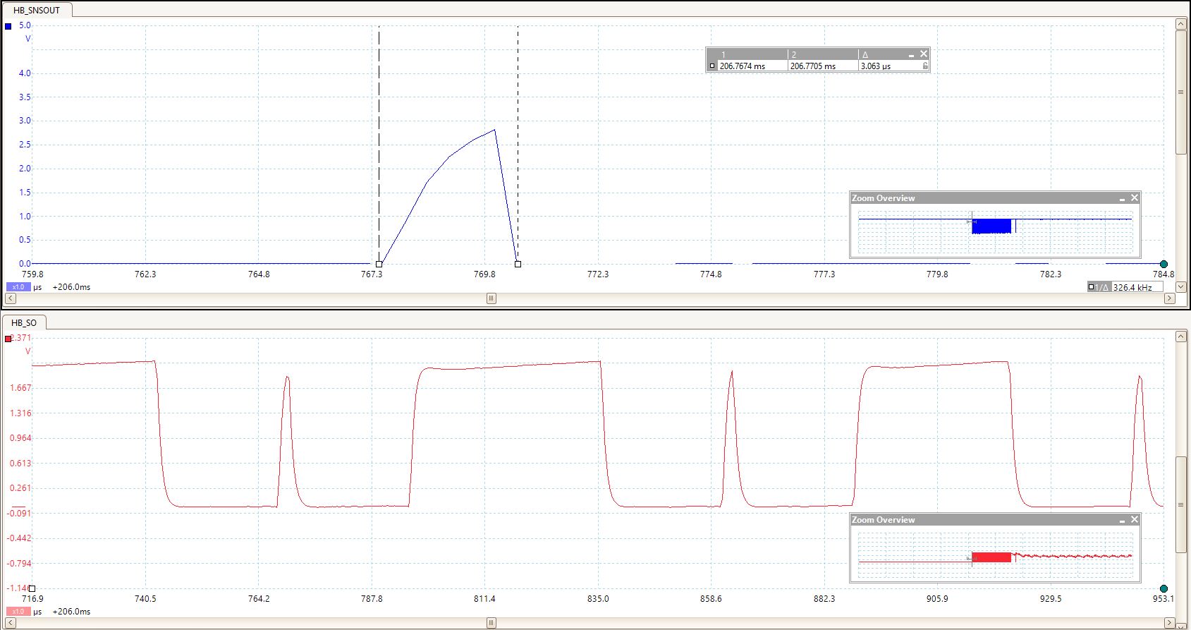
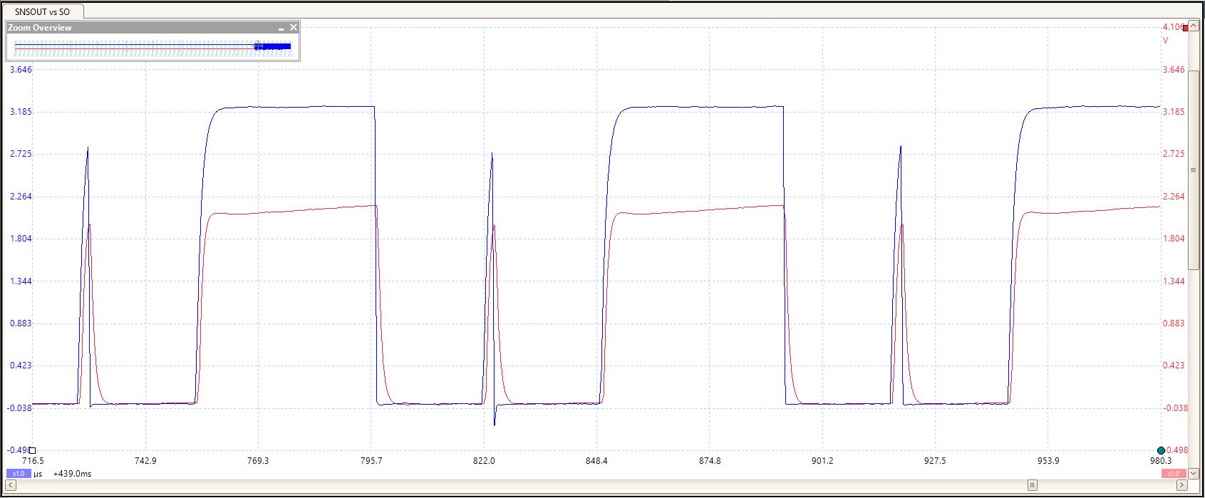
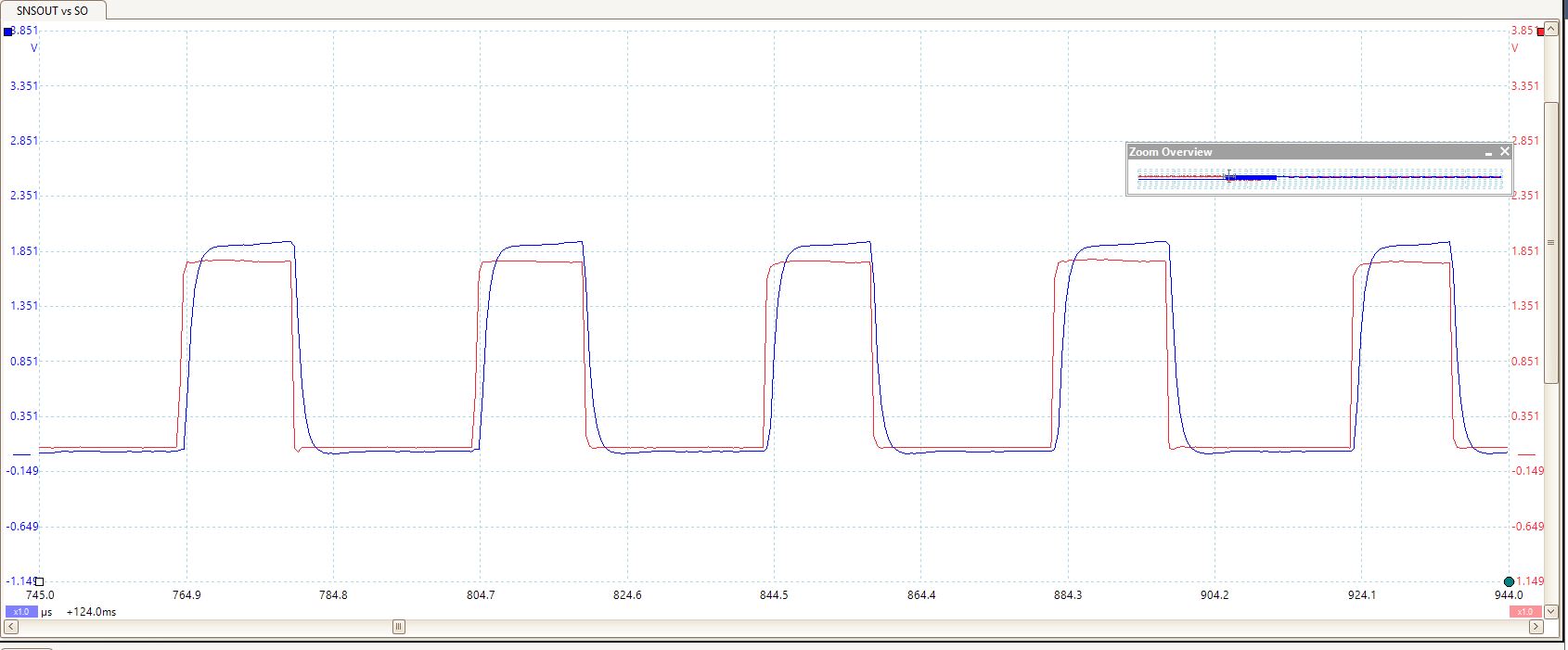
6. If there any more scope captures from the bridge stage (e.g. GL1, GH1, etc.) that you can capture before and right when the current spike occurs, it will help get as much information to me as possible

I can grab some.

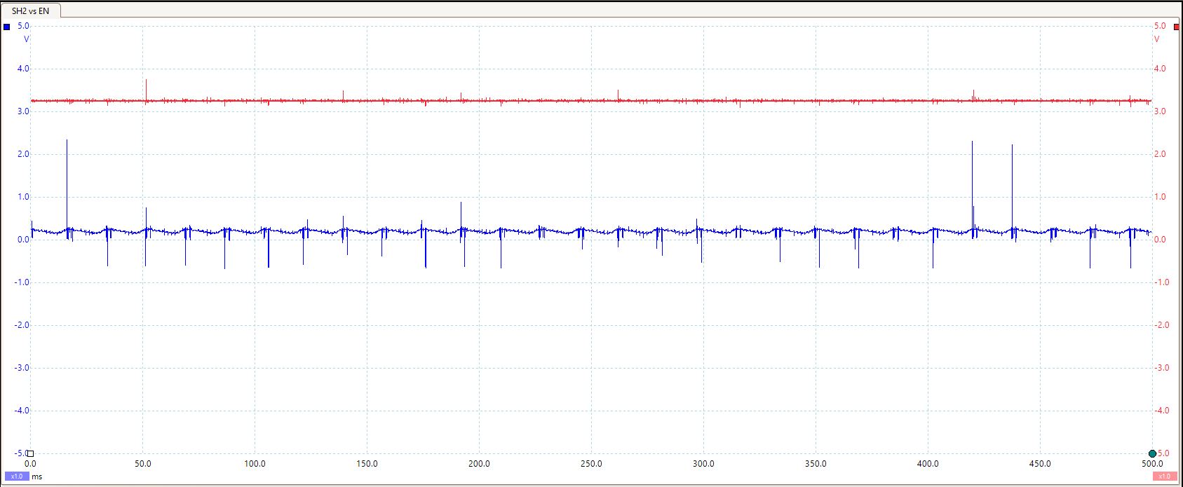
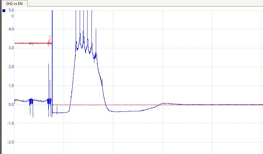
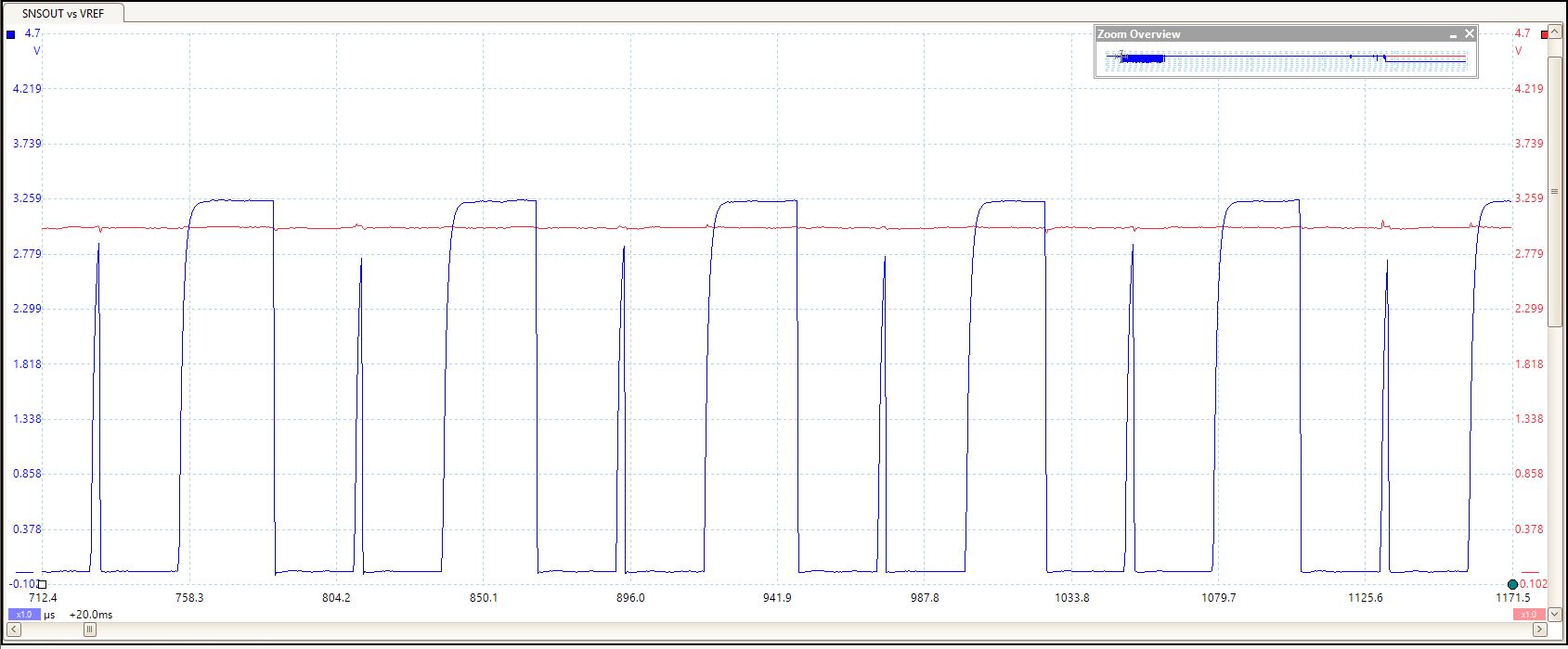
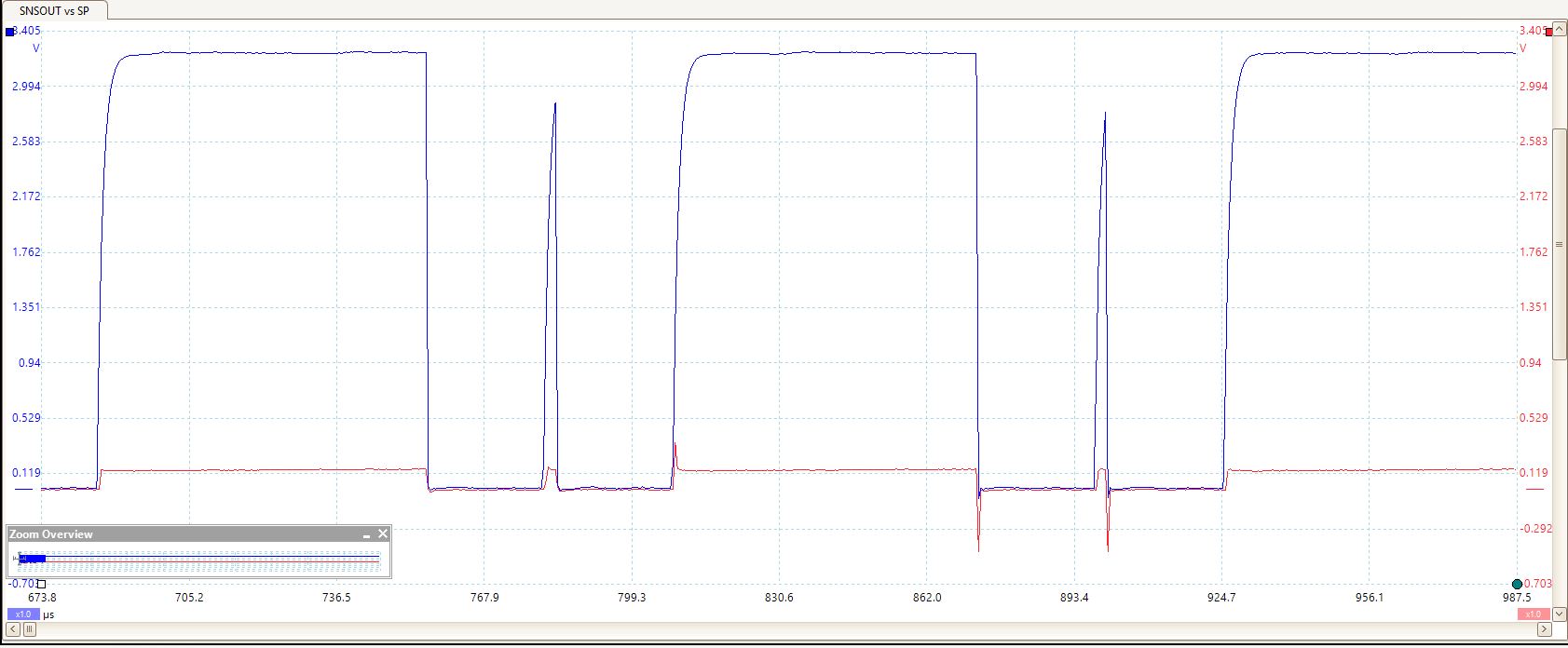
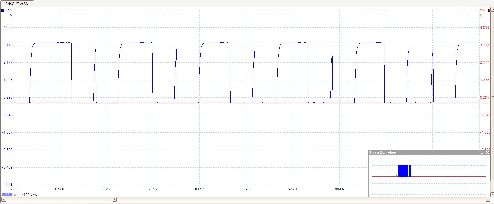
7. From what you are showing, is it fair to assume that, around 696 and 726 ms, GH2 is not being driven by the driver and there are two spikes, one fast at 696 ms and the other prolonged at 726 ms but GL2 is being drivenat 696 ms, correct?

I agree with that. I will try capture additional traces to confirm.

8. Can you share scope captures of the digital PWM signals IN1 and IN2?

Will capture.

9. Does the application circuit have the required capacitor values and voltage ratings? Are the capacitors X7Rs?

With the exception of a cap bettween SP and GND which is C0G, all other caps are X7Rs. All cap values are as per the table below.


Brad.
  • Hi Brad,

    Thanks, please capture (and share what you deem necessary and possible) scope captures of GLx, GHx, SHx, and IN1 and IN2 signals at the time range you have shared. We need to determine if it comes from PWM, from the load, or from something in between.

    Has a test been done with motor and without the load? Further variable isolation.

  • Hi Hector,

    Additional captures...

    GL1 Blue/GL2 Red full capture

    GL1 Blue/GL2 Red 1st zoom:

    GL1 Blue/GL2 Red 2nd zoom:

    GL1 Blue/GL2 Red No Load:

    GH1 Blue/ GH2 Red Start:

    GH1 Blue/ GH2 Red Zoom 1:

    GH1 Blue/ GH2 Red Zoom 2:

    GH1 Blue/GH2 Red Zoom 3:

    GH1 Blue/GH2 Red End Zoom:

    GH1/GH2 No Load: Looks similar on/off characteristic as GL1/GL2 No Load.

    SH1 Blue/SH2 Red Zoom 1

    SH1 Blue/SH2 Red Zoom 2

    SH1 Blue/SH2 Red End Zoom

    SH1 Blue/SH2 Red No Load:

    We are using the 8701E, so there is no IN1/IN2 signal.

  • Hi Brad,

    Thank you very much. I can see what you are zooming into on GH1 Blue/GH2 Red Zoom 3.

    There appears to be an amplitude jump in the signals between each period, as you have indicated.

    Right now, I wonder if the gate behavior you see comes from the digital PWM signal entering the driver.

    1. Is the only scope capture without a load the last one, "SH1 Blue/SH2 Red No Load"? If so, there appears to be no PWMing ocurring. Is there any captures with no load with the Gates/SHx switching?

    2. Can you probe EN and SH1 or SH2 (depending on PH being high or low) to see if the signals entering the DRV and exiting it match in behavior?

    3. In the initial thread, I see Soumya wrote, "We recently dropped our VREF voltage and increased the SP:SN resistance in an effort to reduce peak current draw when running the compressor. " Where the spikes occurring on the application circuit before this change occurred?
  • Hi Hector,

    Yes, the GH1/GH2 zoom 3 shows the additional "failed start" nicely.

    1. It is my understanding that the 8701E handles the PWM internally, whereas the 8701P requires external PWM.

    2. I'll grab that one next... should have it tomorrow.

    3. Originally, we didn't have any current limiting using the VREF or SP inputs. We had large current surges during pump-start, which is what spurred on this change; no 100% PWM D.C.

  • HI Brad,

    Thank you for the clarifications. If you are driving the DRV and depending on current regulation as you appear to be doing, the current spike stems from the load you utilize. There are no spikes when the load is removed, and I interpret load as the compressor and the motor is still connected. Current chopping is activating, and it is dependent on the value of VREF, which I think you know about.

    All of this means that, the amount of current seen while the load is being driven is large and, when the fixed PWM on the Gate signals is goes high, SO passes the VREF value and current chopping activates. You can see that after every one of those "spikes", the off time is the Toff established in the datasheet (25 us).

    It appears the application circuit can be designed to meet a VREF value small enough to handle the amount of current surge on pump start yet large enough to avoid the current chopping you see when driving the load.

  • Thanks Hector.

    That makes sense, that it's the load causing the additional spikes. Our concern was that the intermediate spikes of a much smaller width may be indicative that we are driving something incorrectly. Do you believe this not to be the case, based on all of the signal traces? That it's just a characteristic of the load current draw?

  • Hi Brad,

    The concern I see is in the capture of End Zoom, such as GH1 Blue/GH2 Red End Zoom. When I look at the signals of the explictly stated capture, and compare them to, say, GH1 Blue/GH2 Red Zoom 3, I wonder if there is a difference between both of these capture states that we should be aware of? The end zoom capture has negative spikes on GH1 Blue and the toff time is not met, so I am not certain what is the setup or what is happening right now.

  • Hi Hector,

    I think those negative spikes are ringing due to current surges, and very low energy pulses (the compressor is pulling up to 18 A in it's current current-limited configuration). You can see them in both the "GH1 Blue/GH2 Red End Zoom" GH1 blue trace as well as the "GH1 Blue/GH2 Red Zoom 3" GH2 red trace.

    In terms of a difference, other than the alternating forward vs. reverse drive (as evident in the GH1 vs GH2 active signal), there is no different in the operating conditions of the two traces. Just different parts of a similar test run.

    But I think I see your point... it appears that near the end of the run, the device stops it's internal PWM behaviour. That brings the question of whether the current regulation PWM mode specified in the data sheet Section 7.3.3 is the same sort of PWM behaviour you would expect when operating with the DRV8701P device. It is interesting that it takes a bit of time at the beginning of each cycle before the PWM behaviour starts, as evident in "SH1 Blue/SH2 Red Zoom 2" and "GH1 Blue/ GH2 Red Zoom 2". Why is that?

    Looking at the frequency of operation in "GH1 Blue/GH2 Red Zoom 3", you can see two modes... if you look at the cycle time between a "large pulse" at 658us to the "small pulse" at 718us, you have a 16 kHz PWM, whereas from the "small pulse" at 718us to the next "large pulse" at 746us, it's closer to the design value of 35.7 kHz (f_pwm in the datasheet shows ~ 38 kHz). Is that because if the current limiter doesn't need to PWM, it will override and apply constant drive to the compressor?
  • Hi Brad,

    See replies to points/questions below:

    But I think I see your point... it appears that near the end of the run, the device stops it's internal PWM behaviour.

    -> When you say end of the run, how is the run ended in the application?

    That brings the question of whether the current regulation PWM mode specified in the data sheet Section 7.3.3 is the same sort of PWM behaviour you would expect when operating with the DRV8701P device.

    -> It is. We have not seen behaviour to indicate otherwise.

    It is interesting that it takes a bit of time at the beginning of each cycle before the PWM behaviour starts, as evident in "SH1 Blue/SH2 Red Zoom 2" and "GH1 Blue/ GH2 Red Zoom 2". Why is that?

    -> It can the time it takes to turn on the regulation. I need to look further into the reason why it happens.

    Looking at the frequency of operation in "GH1 Blue/GH2 Red Zoom 3", you can see two modes... if you look at the cycle time between a "large pulse" at 658us to the "small pulse" at 718us, you have a 16 kHz PWM, whereas from the "small pulse" at 718us to the next "large pulse" at 746us, it's closer to the design value of 35.7 kHz (f_pwm in the datasheet shows ~ 38 kHz). Is that because if the current limiter doesn't need to PWM, it will override and apply constant drive to the compressor?

    -> On the 658 us to 718 us drive period, there was not enough SO voltage for it to pass the VREF voltage, so the PWM worked as designed. You can see the PWM off time is 25us.

    -> On the 718 us to 746 us drive period, there was enough SO voltage for it to pass the VREF voltage, so the current regulation worked as designed: The high time of the gate signal is cut off due to current regulation. You can see the PWM off time is 25us as well.

  • I Brad,

    Any further comments or inputs from your end? If no reply by tomorrow, I will close the thread. Thank you.
  • Hi Hector,

    See replies to points/questions below:


    But I think I see your point... it appears that near the end of the run, the device stops it's internal PWM behaviour.

    -> When you say end of the run, how is the run ended in the application?

    --> A tank is filled to a specific pressure and then the EN pin is toggled

    That brings the question of whether the current regulation PWM mode specified in the data sheet Section 7.3.3 is the same sort of PWM behaviour you would expect when operating with the DRV8701P device.

    -> It is. We have not seen behaviour to indicate otherwise.

    It is interesting that it takes a bit of time at the beginning of each cycle before the PWM behaviour starts, as evident in "SH1 Blue/SH2 Red Zoom 2" and "GH1 Blue/ GH2 Red Zoom 2". Why is that?

    -> It can the time it takes to turn on the regulation. I need to look further into the reason why it happens.

    --> Any update on this Hector?

    Looking at the frequency of operation in "GH1 Blue/GH2 Red Zoom 3", you can see two modes... if you look at the cycle time between a "large pulse" at 658us to the "small pulse" at 718us, you have a 16 kHz PWM, whereas from the "small pulse" at 718us to the next "large pulse" at 746us, it's closer to the design value of 35.7 kHz (f_pwm in the datasheet shows ~ 38 kHz). Is that because if the current limiter doesn't need to PWM, it will override and apply constant drive to the compressor?

    -> On the 658 us to 718 us drive period, there was not enough SO voltage for it to pass the VREF voltage, so the PWM worked as designed. You can see the PWM off time is 25us.

    -> On the 718 us to 746 us drive period, there was enough SO voltage for it to pass the VREF voltage, so the current regulation worked as designed: The high time of the gate signal is cut off due to current regulation. You can see the PWM off time is 25us as well.

    --> So given the off time is correct, is there any cause to be concerned with the short duration of the intermediate pulses?


  • Hi Brad,

    To clarify on the second point: the moment the gate signals turn on is the moment right after EN is toggled on in your circuit, is that correct? (using "SH1 Blue/SH2 Red Zoom 2" as the example)

    On the third point, the concern is related to wether or not your system is designed to be pulling as much current as it does that SO trips VREF and causes those shortened drive periods due to current regulation kicking in. If you system is designed for the SO values you are seeing but want to limit the inrush current at the beginning, then the VREF value needs to be increased so SO does not trip VREF during drive time but it does trip it for inrush current to avoid the inrush spike.

  • Hi Hector:

    To clarify on the second point: the moment the gate signals turn on is the moment right after EN is toggled on in your circuit, is that correct? (using "SH1 Blue/SH2 Red Zoom 2" as the example)

    I do not have a trace overlaying SH on EN, but I presume so. It couldn't be off by more than ms though. Would a gap here be indicative of something?

    On the third point, the concern is related to wether or not your system is designed to be pulling as much current as it does that SO trips VREF and causes those shortened drive periods due to current regulation kicking in. If you system is designed for the SO values you are seeing but want to limit the inrush current at the beginning, then the VREF value needs to be increased so SO does not trip VREF during drive time but it does trip it for inrush current to avoid the inrush spike.

    This statement suggests that we should assess increasing our VREF to remove these short bursts. Is the reason for this because the decay in the t_off time is insufficient to bleed through the low-side FETs? I'm curious why it recovers after the next cycle though.

  • Hi Brad,

    I do not have a trace overlaying SH on EN, but I presume so. It couldn't be off by more than ms though. Would a gap here be indicative of something?

    -> Without knowing what nSLEEP or EN are before the outputs change assertion, I cannot assess with 100% confidence what is happening. My train of thought is the device is waking up, as the outputs toggle after about 400 us of being high. Wake-up time parameter has a max value of 1 ms (no typical value).

    This statement suggests that we should assess increasing our VREF to remove these short bursts. Is the reason for this because the decay in the t_off time is insufficient to bleed through the low-side FETs? I'm curious why it recovers after the next cycle though.

    -> It means that you have enough current flowing through the output to that SO trips over VREF. If VREF is increased enough for SO not to trip, you will avoid those shorts PWM bursts. Easiest way to do this task is to measure SO and see up to what value it climbs when it trips over VREF.

    Let me know if you have any further questions. Pleasure working with you.
  • Hi Hector, 

    I'm still hoping we can get some clarity on what's happening.

    Here are captures for SH and EN overlaid at the start, middle and end of a compressor cycle. We had filtering disabled to ensure we didn't hide something telling, so our probes are likely picking up switching and 60 Hz noise as well.

    In an effort to see if we could increase the size of the intermediate spike, we experimented with increasing the voltage reference (assuming that it was getting cut off because it went beyond the current surge threshold). Our threshold was originally set at 2.76 V for a surge of ~18 A. However it seemed that there was very little shift in the size of the intermediate spike even if we increased to 3.02 V. Also, the top of the pulse is much lower than the peak of the larger pulse on either side. We confirmed that there is no filtering on this scope capture of SO. (Vref  increased to 2.85V). We assumed that if we were hitting VREF with the intermediate spike, it would be obvious on the SO capture, but that doesn't appear to be the case. 

    Any further ideas?

    Brad

  • Hi Brad,

    Can you explicitly state the questions and doubts you have? I see the doubt of whether or not SO trips VREF. Any other doubts?

    I am looking into this point.

  • Hi Hector,

    Sure, just looking to understand the behaviour.

    I suppose it boils down to "Why is the h-bridge PWM pulse getting cut so short even though SO did not reach the threshold voltage?"

    Brad.

  • Hi Brad,

    I need to work my way backwards from the comparator output the the half-bridges to see if the issue truly comes from the current regulation. I think it might just be from noise on VREF dropping it and on SP (increasing it) or SN (decreasing it) to make SO - VREF < 0 for those intermediate spikes.

    Therefore, can you expand you capture timestamp to 716 to 953 us and, using SNSOUT (blue color) as a reference signal, do scope captures of:

    SNSOUT with SO
    SNSOUT with VREF
    SNSOUT with SP
    SNSOUT with SN
  • Hi Hector,

    Here are the captures you request...

    SNSOUT with SO

    SNSOUT with VREF

    SNSOUT with SP

    SNSOUT with SN

  • Hi Brad,

    Have you conducted current regulation on the EVM to compare with your design?

    You will receive a private message soon. Expect a request for design files there.
  • Hector: we have not recently, only during the initial design. We'll try that next and see if the same behaviour is present on the dev board.
    Brad
  • Hi Brad,

    Please, keep me informed on your findings. I have a theory as to what might be happening, and the EVM is the next in the verification process.

  • Hi Brad,

    Any updates on the EVM trial? 

    If possible, please share design files via private message.

  • Hi Hector,

    I'm checking on status of the EVM now. Will share files now as well.

    Brad

  • Hi Brad,

    Keep me posted. Checking design files now.

  • Hi Brad,

    I verified the design files. Please, see the private response.

    Do you have an update on the EVM testing?

  • Hi Hector,

    EVM tests are underway, should have results shortly.

    Brad

  • Hi Brad,

    Please, inform me of what you decide will be the next steps and how you will move forward. Thank you.

  • Hi Brad,

    Pinging you for an update here. Thanks.

  • Hi Hector,

    Please find attached snapshots of the EVM board (SNSOUT vs SO signal lines). EVM board does not seem to have those "spikes" we observed on our design. Are there any other signals we should capture on the EVM board? 

  • Hi Akzhana,

    Since the issue appears to only be ocurring on the customer board, no need to further probe the EVM.

    It appears the scope is not capturing potential noise on VREF or SO or other lines. I suggest a trial of probing with a different scope to see if there is noise on customer PCB that has not been captured. If the noise is on SO or VREF or both, the trace(s) is/are cut on the PCB and blue wired to see if the noise reduces and if the problem goes away.

    Layout improvements have been recommended in the private conversation with Brad.

  • Hi Hector,

    Thanks for your response. Just wanted to clarify - 

    If the noise is on SO or VREF or both, the trace(s) is/are cut on the PCB and blue wired to see if the noise reduces and if the problem goes away.

    Are you suggesting cutting SO or VREF traces on our PCB and wire them to EVM and see if we are still seeing the noise? 

    Thanks,

    Akzhana

  • Hi Akzhana,

    Apologies: I did not click the Reply button on the draft response I wrote here last week.

    The suggestion is to cut the the traces with the noise the scope is possibly not capturing (after verifying the noise with another scope or voltage probe) and blue wiring the trace. All on the same board. No EVM in the equation.

    Let me know if any further clarification is required.

  • Hi Akzhama,

    Have you decided or proceeded with next steps? We can close this thread and open a new one once further questions come up. Keep me posted. Thank you very much.