This thread has been locked.
If you have a related question, please click the "Ask a related question" button in the top right corner. The newly created question will be automatically linked to this question.
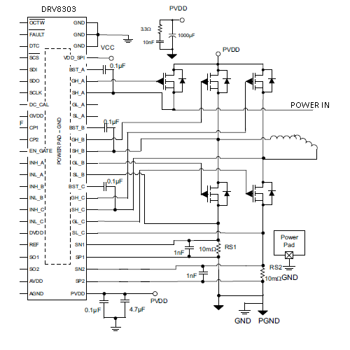
Can the DRV 8303 be used to turn on a N Channel FET with the source connect to power in and the the drain connected to PVDD od the DRV8303? I want to used the FET for reverse polarity protection. Can the trickle charge circuit turn on the FET channel and bypassed the substrate diode to reduce the voltage drop?
Michael,
Please show a schematic of what you are proposing.
We suggest a circuit like the following to most customers: http://www.ti.com/lit/ds/symlink/drv8343-q1.pdf Section "8.3.5.10 Reverse Supply Protection"
Regards,
-Adam
Can the trickle charge circuit charge up the bootstrap cap when the source of the high side FET is
connected to the input power. The driver chip will be powered though the substrate diode until
the channel is turned on. I will also probably add a 10K series gate resistor and the proposed
transistor shutdown circuit.
Michael,
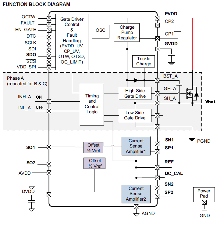
The BST caps can only charge once the LS FETs turn on. Even if the GVDD supply which feeds the BST caps is active once the PVDD is up, the current path for charging the BST caps is dependent on the Switch node (SHx) goes low.
Why do you have "Power IN" marked on the SHA output above?
Regards,
-Adam
Michael,
I misunderstood previously. To clarify, no there is no way for the trickle charge pump to operate if power is applied to the HS Source. Power should not be applied here.
Regards,
-Adam
The POWER IN is the same as Vbat in DRV8343 8.3.5.10 Reverse Supply Protection. I know the bootstrap capacitor is normal charge when the low side of the bridge is turned on, but there is a trickle charge circuit in the driver chip that can maintain gate power ever at 100% on time. My question is can the internal trickle charge circuit in the driver chip turn on the reverse polarity FET. The bootstrap capacitor could probably be much smaller or not needed at all.
Michael,
This is not the case, the power in is PVDD, not SHA. There is no method by which the Trickle charge pump can operate unless the PVDD supply is present.
Regards,
-Adam
Adam
When Vbat of the correct polarity is applied to the circuit, power will be applied to PVDD though the substrate diode of the reverse polarity protection FET. The SHA pin will also receive power and it will be one diode drop above the PVDD until the FET channel is turned on. When the FET is on SHA will be at the same potential PVDD, just like the high side FET in a half bridge configuration.
Michael,
Looking at this again, I think I understand. You want to use only two phases, not a three-phase motor. You are asking if the phase A high-side FET can be used as the reverse polarity protection FET. This assumes you're not using the phase A low side.
If this is true and you use the circuit as you included previously, also reattached here, then this should work.
If you do this, please GND the SL_A pin and keep the gate floating.
Regards,
-Adam