Hello,
I am seeing some odd behavior with bridge A of my DRV8704. When firing coil A at the same chopping current in the "on" direction the high and low gates PWM frantically. As a result I get a slightly lower average current to my load. Firing in the "off" direction, all four gates are completely on as expected and current is limited by the load resistance. My circuit is current limited by the resistance of the coil well below the commanded chopping current. I only write to the torque register and leave the 4 data MSBs set as 0's. I still noticed this issue when commenting out the code writing the Torque register. All other registers are left as the default values. I do not see this issue using the same load on coil B in either firing direction.
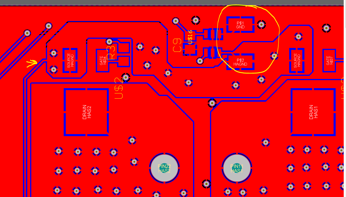
/cfs-file/__key/communityserver-components-mult/cfs-file/__key/communityserver-discussions-components-files/38/Coil-Controller-Rev-1.brd
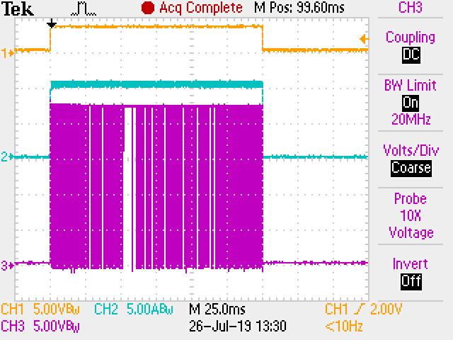
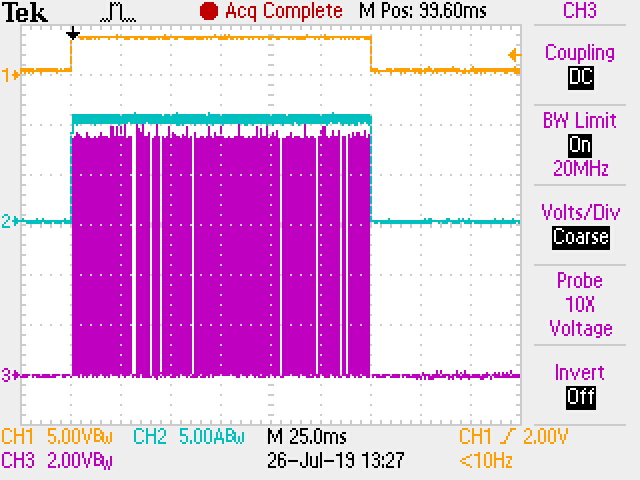
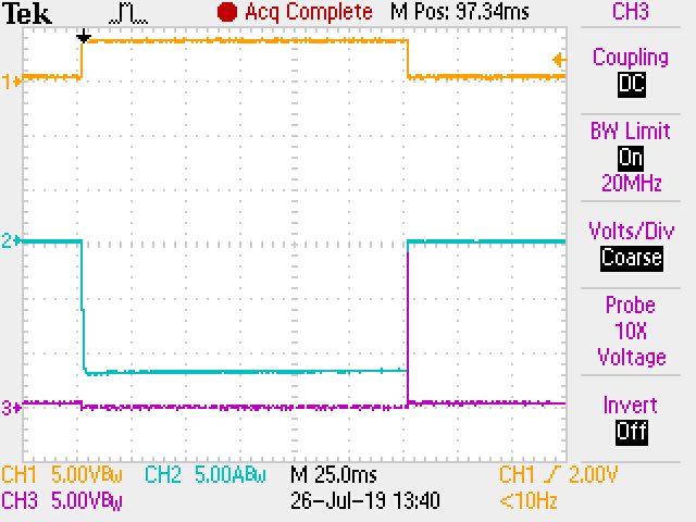
My scope plots have 3 channels captured in them. Ch1 is a trigger signal from the controller's MCU to trigger the oscope. Channel 2 is a current probe clamped to the load coil. Channel 3 is the gate signal.
On Pulse A1HS gate signal.
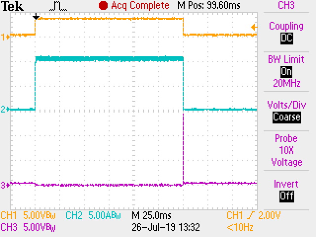
On Pulse A1LS
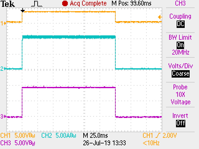
On Pulse A2HS
On Pulse A2LS
And an image of the off pulse for A2LS to show it isn't toggling and the difference in delivered current to the load.
Any suggestions? In my application, I need the maximum current in order to get the actuator to fully travel. That slight degradation in the on-pulse is enough to make the actuator unreliable. Any suggestions hardware or software would be greatly appreciated. This hardware has already been delivered to my customer, I'm hoping a quick software change will fix it.