Other Parts Discussed in Thread: DRV8306
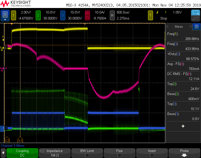
I am using the DRV8306EVM to drive a BLDC motor and seeing some unexpected current flow during one of the stages of commutation where both the high and low side FETs are turned off. In the scope capture below, Channel 1 (yellow) is the Hall Sensor A output, Channel 2 (green) is the voltage on phase A of the motor, Channel 3 (blue) is the low-side FET A gate drive, and Channel 4 (red) is the current through phase A of the motor. Most of this looks as expected, except for the far-right part of the current and voltage waveform (the last 1.5 divisions or so) where phase A is turned off and current is being driven from phase C to phase B. In this part of the cycle, I would expect the current to be zero and the voltage on the motor phase to be ramping up due to back EMF. Instead the voltage is about -1V and the current increases significantly. This seems to suggest that this current is flowing through the body diode of the low-side FET. The waveforms of the other two phases are essentially the same. This current flow through the body diode seems to causing significant additional power dissipation and heating of the FET IC. This was taken with the motor running at about 3000 RPM, but the effect is reduced at lower speeds.
Any idea what could cause this?


