This thread has been locked.

If you have a related question, please click the "Ask a related question" button in the top right corner. The newly created question will be automatically linked to this question.

DRV8889-Q1EVM: SPI Comunication with Stepper Motor

Part Number: DRV8889-Q1EVM

Hello,

I have DRV8889-Q1EVM and operate Bipolar Stepper motor through SPI Protocol.

NOTE:- I am operating DRV8889 of EVM through external MCU instead of on-board MCU(MSP430).

I have some queries to operate Motor by SPI.

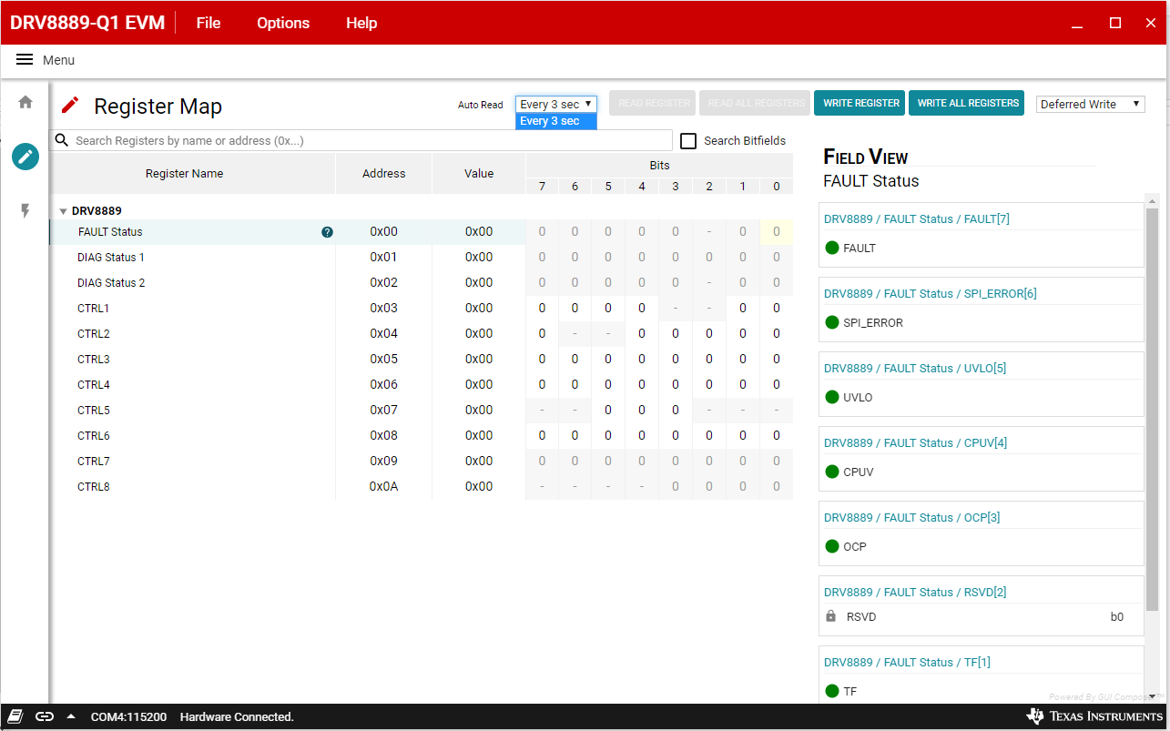
Q-1 In CTRL3, bit 7 is for DIR and description says "Direction input. Logic '1' sets the direction of stepping, when SPI_DIR = 1".

        So here which direction (clock or Anti-clock) is indicated by this bit?

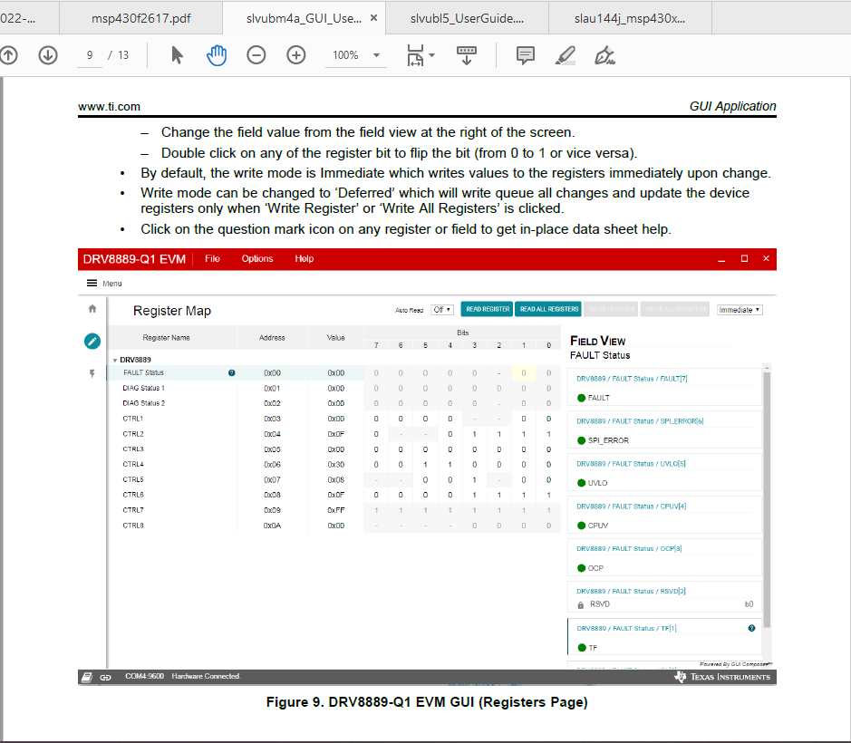
Q-2  I need the full detailed description to configure registers using SPI as the datasheet has not enough information.

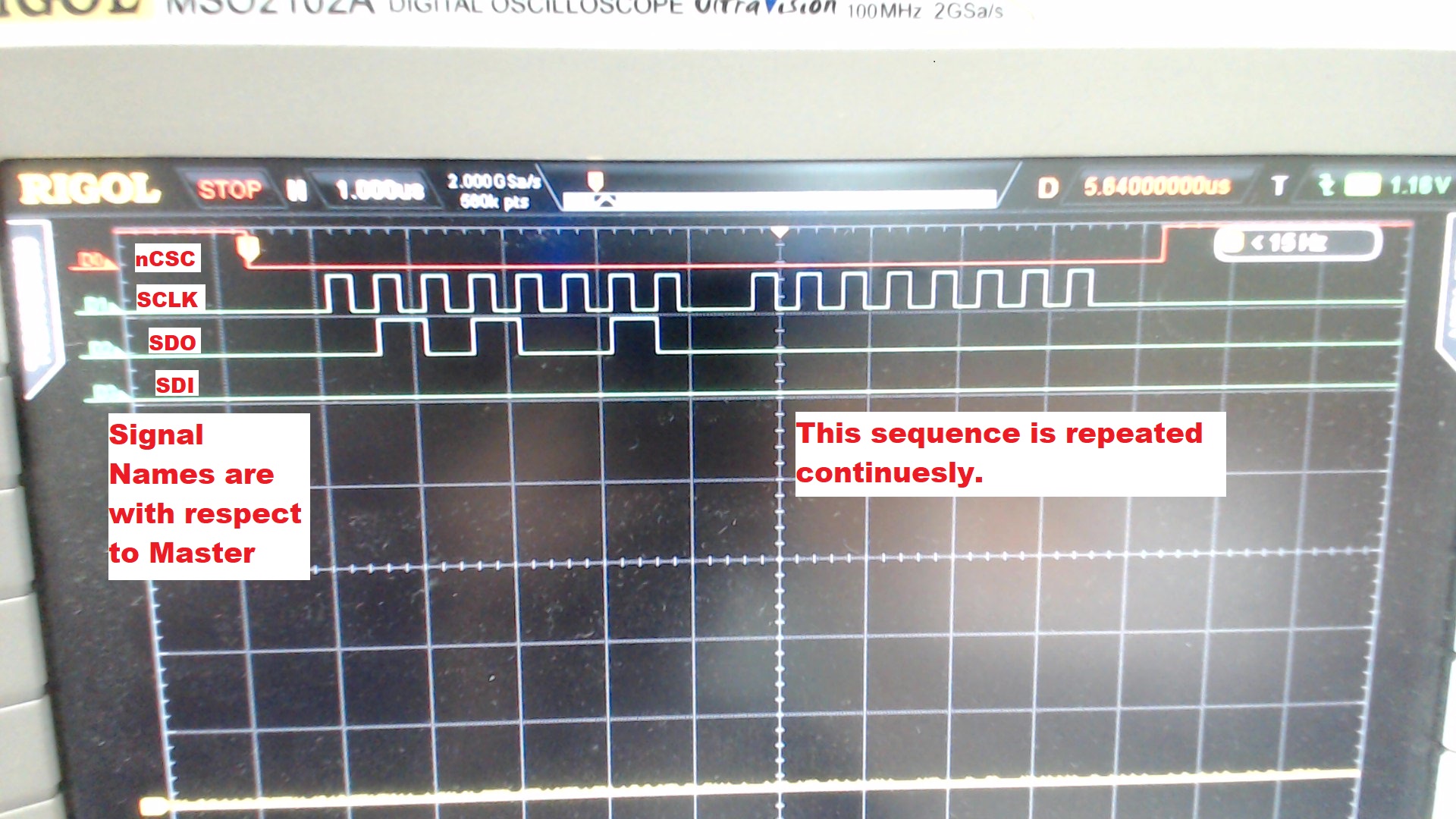
Q-3  Do we have to wait for transaction completion after sending first 8 bits?

Q-4  After power-on the EVM, when I read the CTRL3 register through SPI, received the bit set for the SPI_DIR & SPI_STEP. So Is it correct or Is there any error in reading register?

                 (Here I am sending the 16 bits at a time). 

Regards,

Alpesh


  • 1. "The Stall Detection algorithm compares the back-EMF between the rising and falling current quadrants by monitoring PWM off time and

    generates a value represented by the 8-bit register TRQ_COUNT." To get correct Torque_count value:

    First, please verify and compare the winding current waveform. So, the

    Second, what is the winding resistance? would you reduce the full scale current to 300mA to debug this issue?

    2. To have better understanding the SPI, you can use an EVM to monitor SDI, SDO, SCLK and nCSC pins. When you modify a register bit from GUI, you can check the SPI signal.

    3. After sending first 8 bits, what do you want to do? You can control nCSC signal to start next action.

    4.After power-on the EVM, you have to pull nSLEEP high. And then, you can read CTRL3, Please read a default non zero register and verify the value.

  • Hello Wang,

    Thanks for the Reply.

    1) Our First point is about the DIR bit in CRTL3 register, So Is there any relation between DIR and Stall Detection?

    2) We have Installed the EVM software and connected the EVM board to PC. Datasheet shows options to keep the Auto Read "OFF" for Register Map but in our installed software has only one option to keep Auto Read "Every 3 sec". Also the Button " READ REGISTER" and " READ ALL REGISTERS" are always disabled, I know as per used guide, these buttons will enable after selecting any registers but there is no any information about how to select the registers.  Please find the attached Images for your reference (DRV8889-Q1EVM_Sw_1.png,  DRV8889-Q1EVM_UserGuide_1.png).

    3) As per EVM Code, After sending the first 8 bit there delay of 1us, So Is it compulsory to send first 8 bit then 1us Delay and then next 8 bit instead of sending 16 bit? Please find the Image for your reference(SPI Signals.jpg).

    Regards,

    Alpesh

    DRV8889-Q1EVM_Sw_1.png

    DRV8889-Q1EVM_UserGuide_1.png

    SPI Signals.jpg

    Version of our installed software.

    DRV8889-Q1EVM_Sw_Version_1.png

  • Alpesh,

    1.  There is no any relation between DIR and Stall Detection.

    2. " READ REGISTER" and " READ ALL REGISTERS" are available in the GUI v1.0.0. But, the GUI developer disabled it. I am asking him to fix it. The final GUI will be:

    a. auto-read the register when customers switch the tabs between motor drive page and register map page.

    b. In GUI register map page, make " READ REGISTER" and " READ ALL REGISTERS" button available.

    3. "S" version means the SPI version.

    The waveform shows a read command. The firmware description may be copied from other previous file. It is not accuracy. We will update it to match datasheet.

  • Hello Wang,

    Thanks for the reply,

    For DIR Bit, we found the below statement from Datasheet which resolve my confusion for Direction of Motor,

    "At each rising edge of the STEP input the indexer travels to the next state in the table. The direction is shown
    with the DIR pin logic high. If the DIR pin is logic low, the sequence is reversed."

    Thanks again for the support.

    Regards,

    Alpesh.