This thread has been locked.

If you have a related question, please click the "Ask a related question" button in the top right corner. The newly created question will be automatically linked to this question.

DRV8353: DRV8353 reports GDF when motor was about to spin (using InstaSPIN-FOC)

Part Number: DRV8353
Other Parts Discussed in Thread: LAUNCHXL-F28069M, , DRV8305, CONTROLSUITE

Hi, I've searched through forums and tried all related solutions but nothing seems applicable to my situation

I'm using a custom power board together with LAUNCHXL-F28069M as the control board, while using InstaSPIN-FOC and following the lab guides.

Circuit Diagram Here:
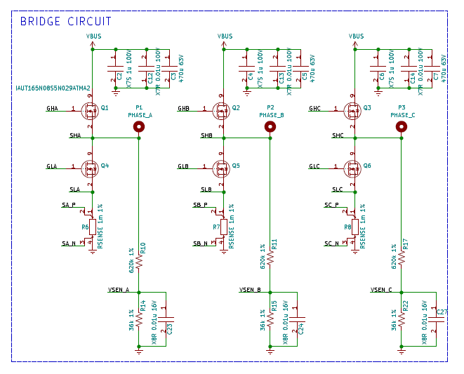
DRV8353 Circuit:

When running Lab01c of the InstaSPIN-FOC (closed-loop current control for signal chain verification), I'm getting a gate drive fault (GDF) from the DRV8305 when the motor was about to spin. What's weird is I'm getting the fault at a specific MOSFET (GL_C) every single time.

My Settings/Parts:

1. Gate drive currents set at (IDRIVEN_LS and HS=900mA, IDRIVEP_LS and HS=750mA)

→ This I get from increasing slowly 150mA to get a fairly acceptable rise time of about ~100nS.

2. All other settings of DRV8353 are set to Default.

3. Using InstaSPIN-FOC @ 45KHz PWM Frequency.

4. Using a IAUT165N08S5N029ATMA2 MOSFET.

5. Power supply is LiPo Battery 4s (about 14.8V ), but alternating between DC power supply of 14.8V.


What I did so far:

1. Tried running the motor using InstaSPIN Lab01b and was successful of spinning the motor.

2. Tried running Lab01c, Lab03x, Lab02x, all same results as described above (motor spins a LITTLE bit (not even half a rotation), then stops due to fault.

3. Tried running on DC power supply (see #5 above), I got a GDF for VG_LC and a UVLO fault on top of that. I only get GDF for VG_LC when running on batteries.

4. Motor should spin using the same parameters because it spins without problems using the same lab exercise but with TI's EVM board.

5. Board is still running and programmable. Tried reproducing with another board but ended up burning the DRV8353 due to improperly setting the drive currents. Will try again after changing the IC.

6. Tried spinning even with the minimum IDRIVE settings, and got the same result. I'm having doubts on increasing IDRIVE further as they may cook the DRV8353 just like what happened to the other boards. Plus, when the gate drive waveforms are checked with Lab01b, they turn on in a timely manner as expected.
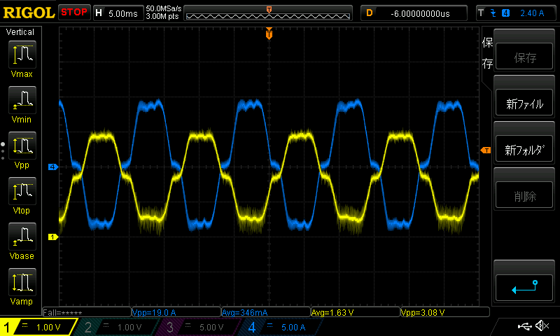
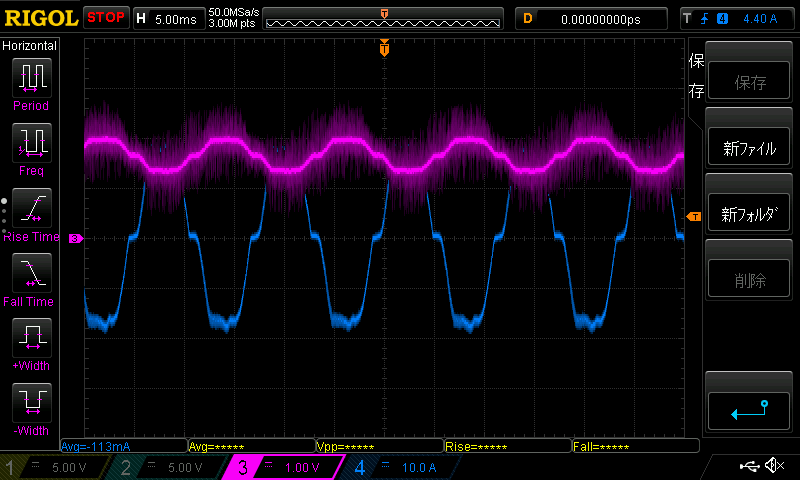
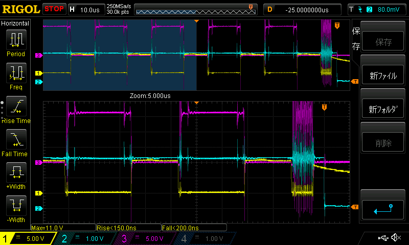
Waveform:

So I tried capturing the gate drive VG_LC, the motor terminal voltage at C, and the FAULT pin just before the error has occurred.

  • Channel 1 (Yellow) is gate drive C
  • Channel 2 (Skyblue) is 
  • Channel 3 (Pink) is Vc (terminal voltage at C)

As you can see, in the last cycle I encountered some weird ringing on the gate drive which in turn falsely triggers the MOSFET (or so I'm thinking), disrupting the signal chain.

What's weird is that the weird noise also appeared on the FAULT signal.

I'd really appreciate if anyone of you would give any hints/ideas/suggestions on how I may further debug this problem.

Motor Parameters (just in case):

Motor: Sunnysky_X2814_900KV

(these settings are copied straight out of user_j5.h):

#define USER_MOTOR_TYPE                 MOTOR_Type_Pm

#define USER_MOTOR_NUM_POLE_PAIRS       (7)

#define USER_MOTOR_Rr                   (NULL)

#define USER_MOTOR_Rs                   (0.0267539211)

#define USER_MOTOR_Ls_d                 (0.00000774756154)

#define USER_MOTOR_Ls_q                 (USER_MOTOR_Ls_d)

#define USER_MOTOR_RATED_FLUX           (0.0059499098)

#define USER_MOTOR_MAGNETIZING_CURRENT  (NULL)

#define USER_MOTOR_RES_EST_CURRENT      (5.0)

#define USER_MOTOR_IND_EST_CURRENT      (-5.0)

#define USER_MOTOR_MAX_CURRENT          (20.0)

#define USER_MOTOR_FLUX_EST_FREQ_Hz     (20.0)

  • Lab01b is just used to verify the PWM, ADC, and power inverting with open-loop control without current sensing feedback. You should use datalog or PWMDAC as lab01b operation instruction in InstaSPIN lab guide, make sure that the below settings are done properly. A more detailed description can be referenced in chapter 5 of InstaSPIN user's guide (SPRUHJ1H).

    1. The current and voltage signals of the motor are sensed correctly.

    2. The correct current and voltage ADC scaling values are set in user.h based on your hardware board.

    3. The sign of the "current_sf" in HAL_readAdcData( ) in hal.h is configured correctly according to the current feedback circuit.


  • Hi Yanming,

    Thank you for your reply!

    It made sense that probably my problem is software-related.
    I will re-check the current and voltage ADC scaling values again.

    However, I will not mark this thread as resolved yet.

    Thank you!

  • Just wanted to check in and see if there is any update from your side, I haven’t heard from you for about two weeks, so I’m assuming you were able to resolve your issue. Please let me know if you have any questions. We would like to close this thread if no further questions. Thanks.

  • Hi,

    So I took your advice and checked my current gains. I also verified the integrity of the current waveforms at my DAC output.

    It seems that I followed the instructions for setting the current gains as of the instructions.

    Here is what I'm getting. The blue line is the one from an external current sensor and the yellow one is the DAC output of the current reading at the same phase.

    I took that waveform when running lab01b (cause anything beyond that won't run).

    Waveform 1: Current Waveform, lab01b, using my Custom Power Section

    It seems that the current waveform output by the DAC was cluttered with PWM noise. I hypothesized that this may be caused by a dirty raw input signal to the sense amplifiers. 

    For comparison, I probed the same signals but using a DRV8305EVM Power Section:

    Waveform 2: Current Waveform, lab01b, using DRV8305EVM Power Section

    Obviously the current scaling will be different because the two boards have different sense resistor values and current sense amplifier gains.

    The current waveform output at the DAC, in this case, is significantly cleaner than Waveform I. So I checked the schematics of my custom power section and noticed the capacitor across the sense resistor is missing. I added a 2.2nF capacitor across the sense resistors to verify if this is indeed the case.

    I tried loading up lab01b again to check the current waveforms if they changed.

    Waveform 3: Current Waveform, lab01b, using custom power section, with Rsense capacitors

    Notice here that the DAC output waveform is now on channel 3. I couldn't notice an improvement on the waveform. Could this just be normal?

    Anyway, I took a video of the phenomenon I'm experiencing. Using lab01c, you can see that at about 00:13 of the video that the motor just spun a little then afterward trigger a gate drive fault.

    https://www.youtube.com/watch?v=zpakGN614Us

    So right now I had run out of ideas. If the current sensing is the cause of the problem, then the next plan of actions can be (1) to re-design the PCB layout, and (2) to use other motor control algorithm that doesn't use current sensing for control. Right now, I'm currently exploring sensorless BLDC control using back-emf detection.

    TL;DR: The problem still has not been resolved. I'm still hoping there are other action steps I can take before I give up FOC. Thank you in advance.

  • What is the rating current of your motor? Do you have to use 1-mohm shunt resistor? What is the sign of the "current_sf" in HAL_readAdcData( ) in the file of hal.h?

    You might change the voltage sampling circuit, use a small sampling resistor and a larger capacitor like 5~10kohm with 22~100nF, and make the voltage filter pole between 400~1000Hz.

  • Hi Yanming Luo, thank you for still getting back to me.

    1. The small motor I am currently using is just for testing. I intend to drive a bigger motor eventually, that's why I designed the hardware to have 1mOhm shunt resistor.

    Current motor:
    www.banggood.com/SunnySky-X2814-900KV-1000KV-1100KV-1250KV-Outrunner-Brushless-Motor-p-1055830.html
    It says in the specifications that it can handle 40A max current in 30 seconds.

    Bigger motor:
    www.xoarintl.com/.../ which will run up to about 97.5 amps of current.

    2. The sign of the current_sf is positive.
    _iq current_sf = HAL_getCurrentScaleFactor(handle);

    3. Thank you for your suggestion on changing the voltage sampling circuit. However, I would like to understand the reason of the need to use a smaller sampling resistor.

    As of the moment, I am experimenting on recovering the source codes of BLDC_Sensorless and InstaSPIN_BLDC from controlSUITE. So far, I was able to spin the motor via sensorless commutation. However, it would be perfect to determine the root cause of the problem here so we can learn from it.

  • I have to add another information that I only noticed just now.

    The phase B shunt resistor terminals SB_P and SB_N are wrongly connected to the DRV8353  (pin 13 and 14). This is an honest design miss. I just noticed the case when I was trying to reconstruct the bus current from the phase currents.

    I'm starting to think that this is causing the failure of the InstaSPIN-FOC to start.

    I'll try to modify the board to fix the circuit then I'll let you know how it goes.

  • And yes, the above was the cause all along. The inverted SB_P and SB_N on the circuit was causing all the mishaps. Consider this case closed.