This thread has been locked.

If you have a related question, please click the "Ask a related question" button in the top right corner. The newly created question will be automatically linked to this question.

DRV8343H-Q1EVM: DRV8343HPHPRQ1 Dont work with VM48V at 4 quadrant (servo) operation.

Part Number: DRV8343H-Q1EVM
Other Parts Discussed in Thread: DRV8350,

Hello dear TI Supporot team
I would like to use the IC in 4 quadrant (servo) operation. By using the INHA pin on high and the INHC pin as pwm Pin.
This works fine with 24V but I need to use 48V. Since the IC is designed for up to 60 V that shoud work I guess using VM=48V.
But it broke after a short time. Is there something you have to consider with VM= 48V? e.g. lower CVCP.
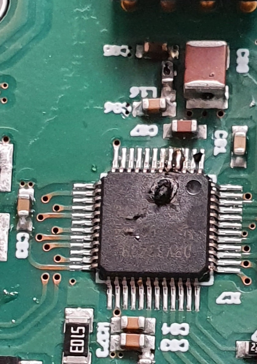
This is Picture of my circuit:
DRV8343H.pdf
Sincerely, Patrick Stubner.

  • Patrick,

    Thanks for posting on the MD forum!

    Do you have an idea of where the damage occurred?

    If possible could you remove the IC from the PCB and measure the resistance of the output pins to GND? Then compare this to a known good device and let us know.

    Regards,

    -Adam

  • Hello Adam

    The damage is near the VM Pin(Pin4). The resistance of the VM Pin to ground is ca 1R. Normal is 1M+ on IC or 25K on PBC.

    Thanks for your help.

    Regards,

    -Adam

  • Hi Patrick,

    Can you confirm that the 1-ohm resistance you measured from VM to GND was with the IC removed from the board?

    Also, in your schematic, can you explain what "+VB" and "POWER_MOT/5.4E" is and whether they are connected or not?

  • Hi Aaron

    The 1-ohm resistance was on my Board and after i unsoildering it on the IC.

    +VB and POWER_MOT have the same source. The POWER_MOT signal do have 2 extra MOSFETS for an securely feature. But for the tests both MOSFETS where open from the start.
    Yes they are connected.

    I hope this coud help you.

  • Hi Patrick,

    Could you clarify what you mean by "open" when you say the MOSFETs are open from the start?

    If VDRAIN and VM are not directly connected together, then a transient at SHx that exceeds VM by more than 10-V could cause damage to the device by exceeding the VCP absolute max value. 

  • Hello Aaron

    POWER_MOT is 48V from the beginning.

    I have atm 22uF + 4,7uF +100nF+33nF at VM is this to mutch or shoud it be ok?

    OK i try to direct conect the VM the C´s to POWER_MOT and look if it goes better.

    Thanks.

  • Hello Patrick,

    Your bypass capacitors at VM should be fine. 

    Let me know the results when POWER_MOT and VM are connected together.

    I would also recommend looking into the DRV8350H if you want a gate driver that is rated for 48-V systems. The DRV8350 is rated for up to 100-V and the hardware variant can support the same circuitry you are using for the DRV8343H-Q1 in your current design. 

  • Hello Aaron

    The connection of POWER_MOT and VM are good and i was able to drive all kind of 48V Motors that we have here :-) . Thanks for your support.

    But now i have the Problem if i want to use it for our Project the Controller isn´t able to lift ca 200kg.

    I have tried different versions of the VDS mode but all with the same resoult. Expect from VDS deactivated .  The controller isn´t able to lift our System.

    We haven an 48V 513W Motor. The RDSon is 13mOhm. That means if i Use VDS =0,6V it woud be more than enough.

    Is there something that i miss in my thoughts.

    Or shoud i deactivated the VDS?

  • Hi Patrick,

    Could you get a scope screenshot of all the following signals:

    1) VDS of high-side FET, (differential measurement between VDRAIN and SHx/DLx)

    2) VDS of low-side FET (differential measurement between SHx/DLx and SNx)

    3) nFAULT 

    I would like to see if there are any voltages that would trip the VDS monitors when the motor is spinning. I'm glad you were able to get your 48-V motors to spin though!

  • Hello Aaron

    I tested it with the DRV8343H-Q1EVM Board.

    And with this TI test board i was able to Lift with our system 600kg without activ cooling. We didnt go higher becuse the MOSFETs got a temperature to 110°.

    I think the MOSFETS that we normaly use are not the best choise for this task with the CSD18540Q5BT MOSFETS from the Board our Test was a great success. But i must look for the reason why our MOSFETS aktivate the VDS way to fast. Maybe the Buffer capacitor is to weak.

    I have only one 220uF. On the Board thare are 1 330uF in the main suppley and on each Phase an 330uF. This may help to stabilize our System.

    Thanks for your support.

  • Hi Patrick,

    I would not expect to see a VDS fault if you are using VDS = 0.6V in your hardware setting. What is the maximum current you are expecting in your application? If you take that and divide it by the RDSON of the FETs (1.8 mOhms), you'll get the maximum VDS voltage that you should use to choose your VDS trip voltage setting.

    It may be possible that a glitch at the rising edge can falsely trigger the VDS monitors, but the best way to confirm is to take scope screenshots I mentioned in the previous post (VDS of high-side FET, VDS of low-side FET, nFAULT).