This thread has been locked.

If you have a related question, please click the "Ask a related question" button in the top right corner. The newly created question will be automatically linked to this question.

DRV8353R: Best way to reduce switching node slew rate

Part Number: DRV8353R

Hello!

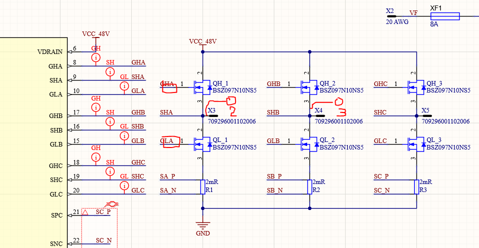
I'm using a DRV8353RS in my design. The switching FETs do not have that much gate charge. So, with the lowest symmetrical gate current setting (100mA) I can't reach the recommended 2V/ns Switch-node slew rate. I measured about 3 V/ns.

What ist the best way to reduce the slew rate?

* Gate resistors?

* Snubber?

* add Miller capacitors?

Regards Konrad

  • Konrad,

    Thanks for posting on the MD forum!

    Yes we recommend 10-20 ohms of gate resistance in this case. If you populate 10 ohms and find that the slew rate is then too slow, you could adjust the IDRIVE setting up slightly.

    I would not recommend a snubber or miller cap in this case.

    More information about this is found in this FAQ and the linked App Note: https://e2e.ti.com/support/motor-drivers/f/38/t/796378

    Regards,

    -Adam

  • Hello Adam,

    I already studied this application note, reduced the current to 50/100mA setting and I'm not sure if 10-20ohm gate resistance will be enough. My MOSFET has 5nC Qgd. With the equations on page 6 I get a rise time of 50ns at 100mA. At 60V that means 1,2V/ns. Everything would be fine.

    In real I measure this switching voltages below. At the end of the switching process the edges have still more than 2V/ns (I think i didn't look exactly in my previous post). If I simulate this with 20ohm gate resistance the edges would not be very much different, I would need about 100ohm to get the double switching time. But 100ohm would be dangerous to get cross conduction.

    My measurements also fit to table 2 on page 15 in the application note. I have 60% Qgd, so my slew rate is 60% higher. The edge is not linear, more exponential, and at the end of the switching process I get a to large slew rate.

    I'm afraid that gate resistors will not solve my problem.

    Any other ideas? Can I see 2V/ns slew rate more relaxed?

    Regards

    Konrad

  • Konrad,

    Please try 10 or 20 ohms and report back. We do not recommend more than 20 ohms.

    Regards,

    -Adam

  • Hello Adam,

    I tried 22 ohms gate resistance. There hardly no difference in the edges as you can see below.

    What can I try next?

    Regards

    Konrad

    with 22 ohms:

    without:

  • Konrad,

    Can you confirm this was tested with the lowest IDRIVE setting?

    Please show us your schematic indicating where the gate resistors are and where your probes are placed.

    Regards,

    -Adam

  • Hello Adam,

    yes, the measuerement was done with the lowest IDRIVE setting.

    The schematic is not that abnormal, the resistors are in the gate lines, probes are placed at the output terminals. I had to insert the resistors by hand so maybe the traces are quite longer than in the final pcb.

    In my opinion the resistors do not help because with e.g. 100mA the voltage drop across the resistor is to low (2V @ 22Ohm). So e.g. the GLA-SPC voltage will go up to 6V in the miller region and the slew rate stays the same. Just if the drivers gate output voltage go into saturation resistor will help.

    In the meantime I use extra gate drain capacitors (39pF), this influences the slew rate, but I get some ringing with high slew rate again. Question is if this short ringing, with slew rate around 2V/ns will be a problem?

    Regards

    Konrad

    Test setting with gate resistors:

    Switching node with additional gate drain capacitance:

  • Konrad,

    Have you found anything else in your testing and debug?

    Regards,

    -Adam

  • Hello Adam,

    no, I was waiting for your feedback.

    In my opinion gate resistor will not help at such small currents. I think I need additional miller capacitance  to reduce the slew rate. My question was about the short ringing. Could that be a problem to the driver IC?

    Regards

    Konrad

  • Konrad,

    I don't see any issues with the latest plots you shared.

    Regards,

    -Adam

  • Hi Adam,

    then we will use this circuit in our redesign.

    Thanks a lot - we can close the issue.

    Regards

    Konrad