Because of the holidays, TI E2E™ design support forum responses will be delayed from Dec. 25 through Jan. 2. Thank you for your patience.

This thread has been locked.

If you have a related question, please click the "Ask a related question" button in the top right corner. The newly created question will be automatically linked to this question.

DRV8308EVM: DRV8308EVM BLDC motor tuning

Part Number: DRV8308EVM
Other Parts Discussed in Thread: DRV8308

We have started DRV8308 evaluation today. Please find scope capture in Trapezoidal mode & sine wave mode.

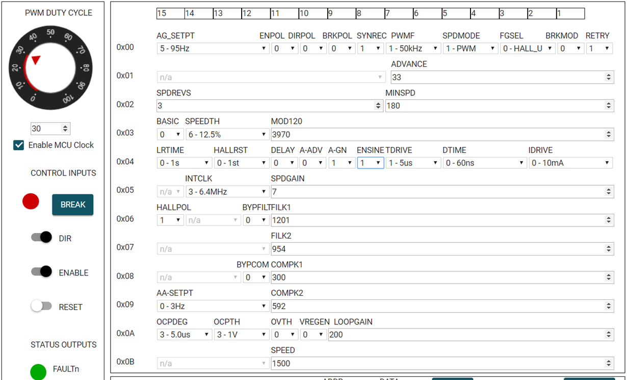
Also, I have attached screenshot of DRV8308_EVM tool in SPI register Mode


Couple of questions -

  1. Is there any guidelines document available for DRV8308 sine wave tuning?
  2. Can you share CCS project database for DRV8308_EVM?
  3. Error observed: Some time it takes more than 1sec to start of motor rotation. Scope capture attached. Channel-1, Vcc=12.5V. Channel-3, current waveform at  one of motor windings. See last pix

DRV8308-EVM Test setup:

DRV8308-EVM is connected with 1) Laptop (through USB cable & Motor is always enabled from GUI) 2) 12.5V DC voltage in 3) Connected to U-V-W winding of BLDC motor 4) connected to 5V hall sensors - 3 pcs

12.5V DC input is pulsating based on needed motor ON-OFF operation

  • Hi Sadashiva Kamath,

    Thank you for posting your questions under the MD Forum!

    1. You can find more detailed information on sinusoidal commutation at this link under section 7.3.4.3-7.3.6. Additionally there are recommendations for tuning the DRV8308 under section 4.2 of this document.  The sinusoidal algorithm is programmed into the motor driver to run efficiently, so there are limited parameters that can be changed for sinusoidal commutation tuning. Are there specific parameters that you have in mind that you would like to have more information on how to adjust?
    2. The CCS project database for the DRV8308_EVM was accidentally dropped from the website, but in the meantime here are the missing CCS project database files: link
    3. Does this 1sec start delay error occur after changing the register values? Or does it also occur when using the preset register values? How frequent does this error occur? Is here any faults recorded during this startup phase?

    Here are a few tests that you can do that might help us discover the root cause of the issue:

        • Would you be able to plot the Faultn pin output along with the Vcc and  the current waveform of one of the motor windings (showing the delay in motor rotation)?
        • Can you repeat step a. but replace the waveform of the Faultn pin with the Enable pin signal?
        • Can you repeat step a. but replace the waveform of the Faultn pin with the PWM signal going into the DRV8308?

    Regards,

    Anthony Lodi

  • Thanks Anthony for detailed answer.

    Does this 1sec start delay error occur after changing the register values? Ans: Yes,This 1sec start delay error occur after changing the register values. Register values changed initially once after power-up and ENABLE is always enabled in GUI after that. Only 12.5V (DC input) was toggled based on needed motor ON-OFF.

    Or does it also occur when using the preset register values? Ans: 1sec start delay was not monitored when using the preset register values.

    How frequent does this error occur? Ans: 1sec start delay occurrence is around 25%. It works perfectly on 75% of  iterations i.e., without start delay. it occurs once in around ~4 min.

    Is here any faults recorded during this startup phase? Ans: Faults are not observed.

    Is EVK firmware works correctly if a) EVK's USB cable is always connected to laptop with MOTOR-ENABLE made ON initially in GUI (GUI is not touched later during motor ON-OFF operation) and 2) only motor voltage (VM =12.5V) toggled when motor ON-OFF needed?

    I think firmware tweaking may be needed?

    I will provide other details tomorrow as I'm WFH today.

  • Hi Sadashiva,

    Thank you for your response.

    What is the exact connector or signal on the EVM board that are you are probing to plot the yellow scope trace? The traditional method to control the ON-OFF of the motor is by using the ENABLE button of the GUI, so we will need to take a closer look at the method you are using to see if that is causing some issues.


    Regards,


    Anthony Lodi