This thread has been locked.
If you have a related question, please click the "Ask a related question" button in the top right corner. The newly created question will be automatically linked to this question.
Tool/software: Code Composer Studio
Hello,
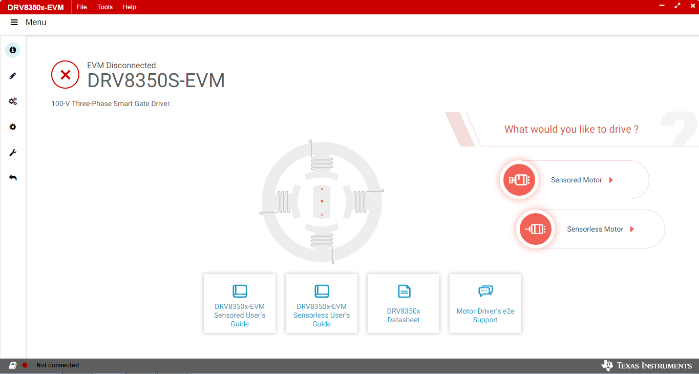
I'm currently working with DRV8350S-EVM and trying to operate it in sensored mode. In my setup I have downloaded the GUI and I'm giving 5 V supply to hall sensor using the on-board option available through the 3 pin header. When I start the GUI the driver-motor system is automatically configured as sensorless after COM port detection and enabling, after which the sensored option is not visible in the GUI.
I wanted to know whether there are any other hardware or software configuration that I'm missing in order for the EVM to work in sensored mode?
Regards,
Abhishek K Singh
Hello Abhishek,
The GUI only works with sensorless FOC. You need to go to the EVM page and download the sensored FW. I'll provide the link here:
Note, the firmware is not in a GUI type format. It uses Code Composer Studios and you will be modifying code the code directly to get it the motor to spin. Installation for CCS and the rest of the FW is found in the user guide, section 3:
More information about spinning the motor and the sensored FW is in the sensored software guide:
Best,
-Cole
Hello Cole,
Thank for replying to my query.
1) In the GUI option for sensored mode is given for DRV8350S-EVM.
2) I wanted to know if I can use GUI in Sensored mode somehow? Is it possible to if I upload sensored code to the MSP430 micro-controller through the firmware and then start the GUI?
3) Also is it possible to operate in sensored mode use sensorless page of GUI e.g. can I use 1 x PWM mode in sensorless condition but the Hall sensor signal are going directly to DRV8350S motor driver? There are some resistors namely R46, R48 and R51 provided on board which are DNP and if 0 ohm resistor is populated at their place then the hall sensor signal will be directly connected to the motor driver. If I chose 1 x PWM mode and hall sensor signals are going directly to the motor driver then will this create any issues?
4) In section 4.3 of DRV835x-EVM user guide it is mentioned that:
"If using the sensored firmware on the MSP430F5529, connect a brushless DC motor Hall sensor inputs to hall sensor header and solder the unpopulated R82, R84, and R86 0 ohm resistors. If using sensorless firmware, this header can be left unconnected."
I was unable to find R84 and R86 on my board and R82 was already connected. Do I have to consider this also when using sensored mode?
Regards,
Abhishek
Hello Cole,
I found some errors in the sensored code when I was building the project "DRV8350X_MSP430F5529_Trapezoidal_Sensored_BLDC". I'm attaching the screenshot of error:
I changed the identifier name to "sensoredTrapController" after which upon building this error was not being shown. Is what I gave done correct?
Can you please send me the DRV8350X sensored project?
Also after downloading the sensored code on the MSP430 using CCS can I use GUI in sensored mode? I saw a parameter called ALGO_ID which is used to identify the type of firmware on the MSP430, Is the GUI using this parameter to identify the EVM in sensorless mode automatically upon USB connection?
Regards,
Abhishek
Hello Abishek,
I plan to give a better reply before 12/18/20.
You're right, I am mixing up part numbers from the same family.
If you're intent is to use the 1x PWM mode, feel free to populate the R46, R48 and R51 and note the PWM signal needed for INHA. The CCS firmware projects are used for more involved commutation.
Best,
-Cole
Hello Cole,
Thank you the earlier reply, but can you elaborate on the issues which I had raised.
Thank you,
Abhishek
Hello Abhishek,
Sorry for the delay.
Here's a simple list of steps to help you (but mostly others) to use sensored FW with the EVM:
This firmware only refers to the sensored trapezoidal commutation. This hardware does not support FOC. To reiterate, the DRV8350x does support FOC but the specific purchasable HW, DRV8350S-EVM, is not compatible.
Best,
-Cole
Hello Cole,
Thank you for clearing my queries on DV8350S-EVM. I have followed the steps as given by you and I'm ale to access "sensored" mode of GUI after downloading sensored FW on the EVM.
I tested the performance by trying to run a Hall sensored BLDC motor. But it was showing "hall sensor is invalid" in Fault detection on GUI. Then I tried calibrating the hall sensors by using "Motor calibration" option in GUI, but i required tuning of hall calibration parameters. I tried tuning but sometimes "over-current fault" and other times "calibration unsuccessful" was displayed in Fault detection. I tried searching any detail on hall calibration in the documentation of EVM but was unable to find one.
Can you please send some documentation on Hall calibration in this EVM.
Regards,
Abhishek
Hello Abhishek,
The team is out of office on 12/24 and 12/25 due to public holidays. Please expect a response on 12/28.
Thanks,
Matt
Hello Abhishek,
Let's verify some hardware to start.
Can you R45, R43, and R42 are populated with 1k ohm resistors? If they are populated, can you spin the rotor by hand when the board is powered and ensure hall A, B, and C toggle as expected? We're assuming the hall sensors are non-inverting outputs.
After that can you verify that the phases are connected to the corresponding hall sensors correctly? We have an FAQ on the criteria, you just need an oscilloscope.
[FAQ] How to Ensure Correct Alignment of Hall Sensors and Your Motor - Motor drivers forum - Motor drivers...
The calibrate halls function essentially tries to align the motor by pulsing some current through it to make the rotor align to known position where expected hall signals will be known. If they do not match, the error will be thrown.
Best,
-Cole
Hello Cole,
Thank you for your help regarding DRV8350S-EVM
Regards,
Abhishek K SIngh