This thread has been locked.

If you have a related question, please click the "Ask a related question" button in the top right corner. The newly created question will be automatically linked to this question.

DRV8353R: Observing random jitter movement in BLDC motor less frequently at power ON

Part Number: DRV8353R
Other Parts Discussed in Thread: CSD19532Q5B

Hi,

I have designed a 36v BLDC motor controller using DRV8353RS by following the guidelines given in the datasheet

Everything works fine but I observe a sudden motor jittery movement at the time of power ON randomly but less frequently though all the input pins (INHx, INLx) are tied low while enabling and initializing the DRV chip

Power Supply:

1. I use dual power supply

2. 15v to Vm

3. 36v to Vdrain

4. 5v to HALL sensors

5. 3.3v to MCU

Sequence I follow while initializing to 1x PWM mode:

After power ON 500ms delay

1. Make BRK, DIR, 3 HALL (used external transistors for each pin to pull them low) and PWM pins low

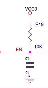
2. Set enable pin high

3. Change PWM mode to 1x PWM from default 6x PWM and change GATE current settings

4. Release HALL pull downs (by disabling the external transistors on each pin)

5. Release brake

delay(50ms)

6. Start PWM 20KHz

Register Values configured as below:

REG 2 : 0x440

REG 3 : 0x307

REG 4 : 0x337

REG 5: 0x29D

Rest are default values

Issue:

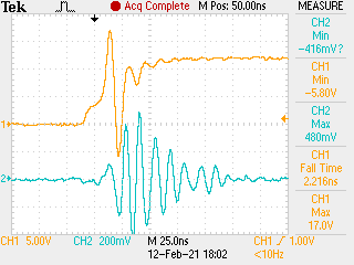
Motor runs fine and no spikes at any of the GATES, but for some reason only while POWER ON I see motor makes a sudden movement (may be for only few milli seconds) and stops, afterwards everything seems fine

What could cause above behavior and how to overcome this, please help

thanks, 

Chandra

  • Hello Chandra,

    Can you share your schematic? Additionally, can you capture on an oscilloscope each INHx and INLx input when you power on to check for any unintentional voltage spikes?

    It looks like you are already addressing the power ON of the DRV8353R. If you are tying your Hall Sensors directly to the DRV8353RS, the DRV8353R will power ON in 6x PWM mode and interpret the Hall Sensor Signals that way. The driver will not be in 1x PWM mode until you perform a SPI write to the device to change the PWM MODE. You are disabling power to the Hall output pull-up until DRV8353R power-up is completed and you have changed the PWM MODE to 1x PWM.

    Thanks,

    Matt

  • Hi Matt,

    Thank you for the inputs, sure will capture the waveform and let me see are there any voltage spikes

    thanks, 

    Chandra..

  • Hi Chandra,

    Please do let me know, and if you can let me see those waveforms myself!

    Thanks,

    Matt

  • Hi Matt,

    After probing INLx, INHx and various points finally I could find a sharp overshoot and undershoot only on GLA and GHA pins consistently while I change the PWM mode from 6x to 1x PWM, all other pins like GHB GLB GHC and GLC are fine

    Register settings sequence as below

    Drive all input pins to low (INHx and INLx)

    1. Enable high

    delay(20ms)

    2. Set drive strength for HS as P_HS = 50mA N_HS = 300ma

    3. Set drive strength for LS as P_LS = 50mA N_LS = 300ma

    4. Change 6x PWM to 1x PWM ----> spikes are seen only after this independent of drive strength

    Did not release brake yet and HALL inputs are also pulled low 

    Snapshot of GLA (yellow) and BRK (INLC) (cyan)

    I guess when the overshoot at break pin crosses its threshold I am seeing a jitter for a moment at this point


    Snapshot of GLA (yellow) and GHA (cyan)


    Why there is an overshoot only on GLA pin (I followed the same schematic used in DRV8353RS evaluation board except no gate to source capacitance)

    thanks, Chandra..

  • Hi Chandra,

    Your high-side gate is staying OFF, and your low-side is turning ON. I assume this is brake mode entry and all three phases have the low-side ON after switching to 1x PWM mode.

    You may want to try setting the COAST bit over SPI before you switch PWM modes (address 2x bit 2). This would make sure the motor does not immediately go to BRAKE state when you switch PWM modes - instead it is in COAST. You can clear the COAST bit after switching PWM modes.

    What MOSFETs are you using? The low-side gate GLA is showing around -5V negative spikes, which is pretty close to the abs max rating. Your high-side gate is showing almost -10V (close to abs max). This may indicate that your IDRIVE setting is too high. Given that you appear to switch in <25ns, this would also indicate that the 50mA IDRIVE source and 300mA sink setting you have chosen are  too high. ([FAQ] Selecting the Best IDRIVE setting and Why this is Essential)

    Thanks,

    Matt

  • Hi Matt,

    >>> This may indicate that your IDRIVE setting is too high. Given that you appear to switch in <25ns, this would also indicate that the 50mA IDRIVE source and 300mA sink setting you have chosen are  too high

    Ans: 50mA is the lowest possible setting in DRV chip but still the spike could overshoot in <25ns. If IDRIVE is more then I wonder why other GLx pins does not have this behavior as they also share the same IDRIVE setting. All the mosfets are same csd19532q5b as used in evaluation board.

    Also after recovery from this spike I could run the motor with GLx rise time of ~400ns, it is this GLA only at the time of PWM mode change it drives so fast


    thanks, Chandra..

  • Hi Chandra,

    You are correct - 50mA is the lowest source setting. If during normal operation you do not see this I have less concerns.

    3. Change PWM mode to 1x PWM from default 6x PWM and change GATE current settings --> If you change the IDRIVE settings *after* you change the PWM mode over SPI, the driver will use the default IDRIVE setting when applying the BRAKE. Can you confirm if you are setting IDRIVE before or after you change the PWM mode? i.e. write REG 2 last. In your second message it looks like this order is correct, but in the first message it is unclear.

    • Can you double-check this?

    Using COAST bit to avoid the behavior:

    • Can you try asserting the COAST bit until the PWM MODE change happens?
    • Does this spike still occur when you change the PWM MODE, does it happen when de-asserting COAST, or does it go away?
    • Can you also try releasing nBRAKE low to high after using the COAST bit?

    If this is only seen on phase A then it looks like you are getting into the 1x PWM ALIGN state (all inputs "1"). I can't see how that is happening but the behavior aligns with what you are seeing.

    • What is the state of the PWM pin?
    • Can you share your schematic?

    Thanks,

    Matt

  • Hi Matt!

    I have the same problem, when the enable signal is applied, a pulse can be seen on the shunts.
    In this case the input current is limited by the source and the pulse duration is about 250µs. 

  • I have solved this problem. Before the enable signal you need to set all INHx and INLx signals to 0 and keep them in this state until the end of the SPI configuration. Otherwise these signals will drive the transistors. 

  • Hi Alexey,

    That is correct!

    Thanks,

    Matt

  • Hi Matt,

    After a lot of debug I found the issue for the sharp spike at power ON,

    In my design DRV's Enable, Direction and HALL sensor input masking pins are connected via i2c IO expander.

    Its reset pin is connected to resistor and capacitor as below [logic 0 is under reset and logic 1 is out of reset]

    At power ON this capacitor at reset pin takes few micro seconds to charge up to 3.3v, but while the voltage was ramping up half way I started initializing the IO expander and Enabled the DRV chip, at this time the HALL sensor mask was not yet latched up making all three HALL sensor inputs high which drives the MOSFETs to align state with default highest IDRIVE setting. This caused the sharp overshoot

    My suggestion would be that in future DRV chips please keep its IDRIVE default settings to lowest possible at POR, this will help us experimenting with DRV chips safely

    Thanks a lot for all your suggestions, now I am setting the BRAKE bit first and only then changing the PWM mode

    regards, Chandra..

  • Hi Chandra,

    Glad to hear that you figured it out! I hope my guidance was helpful through the process.

    We do have this as a recommendation for the next generation of devices: default to lowest IDRIVE setting on power-up.

    Thanks,

    Matt