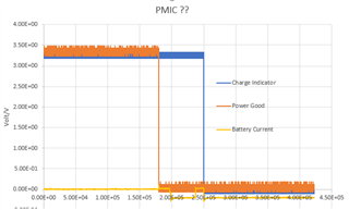
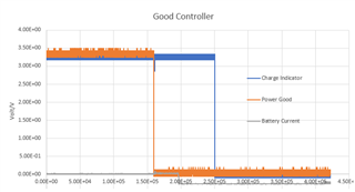
Can I reopen CS0433712 case please. I have done further testing and have removed the regulator as requested and I also have plots showing difference in the PMIC functionality. Thanks

-
Ask a related question
What is a related question?A related question is a question created from another question. When the related question is created, it will be automatically linked to the original question.