This thread has been locked.

If you have a related question, please click the "Ask a related question" button in the top right corner. The newly created question will be automatically linked to this question.

USB-PD-CHG-EVM-01: TPS25750 overwrites BQ25792 PROG Pin

Part Number: USB-PD-CHG-EVM-01
Other Parts Discussed in Thread: BQ25792, TPS25750, USB2ANY

Hi,

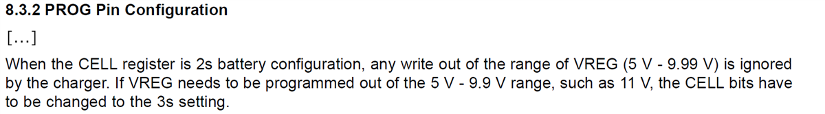
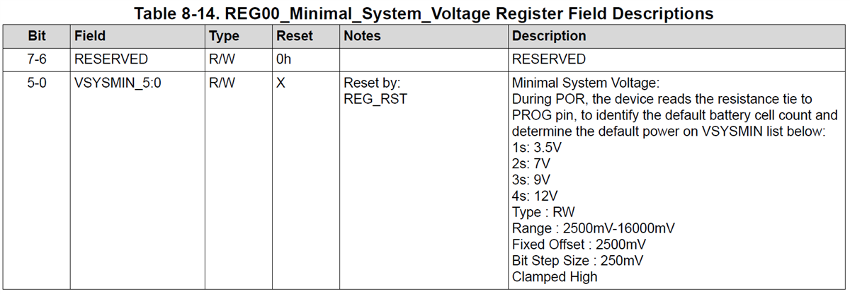
I just connected a 4S cell pack to the BAT pin of BQ25792 and wanted to charge it directly using USB-PD. Before I connected the battery pack, I switched the Jumper from JP2 (3s) to JP3 (4s) to select the right resistance to the PROG Pin. Then I connected an USB-C power supply to the USB-PD-CHG-EVM-01. But the STAT Pin (D1) starts to blink as described in the datasheet of BQ25792: "Charge suspend (A fault condition which disable charging)".

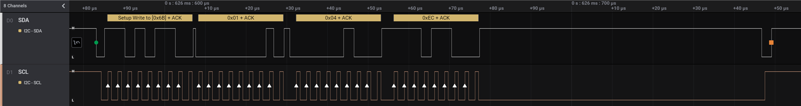
So I checked what TPS25750 sends to BQ25792 over I2C for initialization using the pin header J7. In the first phase, TPS25750 reads from EEPROM (I2C address 0x50). In the second phase then it writes to the BQ25792 (I2C address 0x6B).

It configures the BQ25792 to set

  • the Charge Voltage Limit Register (reg. address 0x01) to 0x04 0xEC = 1260 * 10mV = 12’600mV = 12.6 V => 3s cellpack
  • the Charger Control 1 (reg. address 0x10) to 0x80 => disables the Watchdog

So the PROG Pin doesn't have an effect because the TPS25750 oversteers it afterwards.

That's why the STAT Pin blinks: Overvoltage of the battery (current battery voltage is 14.2V).

How can I configure USB-PD-CHG-EVM-01 using a host microcontroller (Tiva or different ARM based microcontroller) so that it uses a 4s cellpack?

I checked documents like the following, but only found something using a GUI to produce a binary file and USB2ANY or Aardwark devices to flash the file.

Regards,

Andreas

  • Dear Andreas,

    I just tested the configuration you described. First I moved the jumper to 4s or JP3. I then attached a 15.6 V Battery. Next, I attached a PD source for 9 V. The battery started charging and regulation was 16.8 V (this is the default charge regulation for a 4s battery). Because the charger is in the 4s state, any attempt to write 12.6 V regulation will fail. Can you please double check your setup?

    This means that if you program the TPS25750 for 12.6 V regulation, but you select 2s or 4s jumper setting, the regulation will be 8.4 V or 16.8 V respectively. Please read "Section 9.3.2 PROG Pin Configuration." 

    If you would like to program the BQ25792 for its charge voltage, charge current, pre charge current, and termination current, please follow https://dev.ti.com/gallery/info/1769824/TPS25750_Application_Customization_Tool

    You will need to download the binary by clicking, "Generate Full Flash Binary." For the USB-PD-CHG-EVM-01 I then used Flash Center GUI to program the device using the J5 connector and an Aardvark by Total Phase. Please make sure there is power on the BAT pin when doing this. This flash process is detailed in the USB-PD-CHG-EVM-01 User Guide on Page 12.

    Thanks,

    Mike Emanuel

    Please click "Resolved" if this answers your question.

  • Hi Mike,

    I don't have a Aardvark by Total Phase at hand.

    I just connected the battery pack directly without flashing anything, so the EEPROM content is directly from TI. Here is an extract from the I2C traffic (Saelae Logic 2):

    The "TPS25750_Application_Customization_Tool GUI" is a bit intransparent. I don't know how the GUI transfers it and where it transmits to. To the CAT24C256WI EEPROM Flash?

    What is the format of this binary file?

    How can I upload the binary file ("Generate Full Flash Binary" from GUI) through a microcontroller (preferably an STM32, but there are Tiva MCU around)?

    You answered another question here: BQ25792: USB PD test solution

    About c)
    How do I configure the TPS25750 to pass-through commands to BQ25792 resp. the CAT24C256WI EEPROM/Flash?
    In the following document I couldn't find anything with keywords like "pass-through" or "proxy" or something like that:
    TPS25750 Host Interface Technical Reference Manual

  • The format of the file is Intel Binary Hex. You need to use an EEPROM 24 series programmer. You can use this programmer attached to load the file, no power to the board is required. https://www.amazon.com/Organizer-Socket-Adpter-Programmer-CH341A/dp/B07R5LPTYM/ref=sr_1_5?dchild=1&keywords=eeprom+programmer&qid=1621625310&sr=8-5

    Thanks,

    Mike Emanuel

    Please click "Resolved" if this answers your question.

  • I checked what the BQ25792 registers are:

    reg=0x00 name=Minimal System Voltage  size=1 data=0x26
      VSYSMIN                 = 9.50
    reg=0x01 name=Charge Voltage Limit    size=2 data=0x06 0x90
      VREG                    = 16.80

    So the TPS25750 wants to write 12.6 V to the REG01_Charge_Voltage_Limit but failes as you already said and written in the datasheet:

    Funny that 0x00 REG00_Minimal_System_Voltage Register is not in the range of what the PROG pin says. When the J3 (4s) jumper is on, the VSYSMIN register is at 9.5V, not 12V:

    And the TPS25750 writes only these registers, that doesn't include 0x00 REG00_Minimal_System_Voltage Register.

    0x01	Charge Voltage Limit
    0x10	Charger Control 1
    0x06	Input Current Limit
    0x03	Charge Current Limit
    0x14	Charger Control 5
    0x11	Charger Control 2
    0x08	Precharge Control
    0x09	Termination Control

    Strange, strange.

    As you already mentioned about "double checking my setup"... probably I connected the batteries BEFORE I switched from 3s to 4s.

    Now it works resp. the adapter charges the batteries.

  • I checked the datasheets of the Flash/EEPROM CAT24C256WI.

    I can program it normally using any I2C master. My beloved STM32G071 can do it:

    • Binary file size: 30.8 KB
    • MCU flash size: 128 KB
  • Please make sure the batteries are removed before switching the jumper settings. 

    I input your data for MinSys of 0x26 into register 0x00 and it gives me a MinSys of 12.000 V. Please check your register settings.

    Remember to power cycle the board completely after programming the flash.

    Is there anything else I can help with?

    Thanks,

    Mike Emanuel

    Please click "Resolved" if this answered your question.

  • Oh, I missed the "Fixed Offset" of 2500mV in my calculations.

    9.5 + 2.5V = 12V

    I'll rise another topic (new question) about ship FET this evening...