Hi Team,
I'm designing a -15V power supply for my circuit with LM137.
My input is -15.5V. The maximum load current is about 500mA.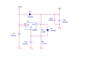
R1=120 Ohm and R2 is 1.31K
Is there any problem with the design?.
Also, I want to know 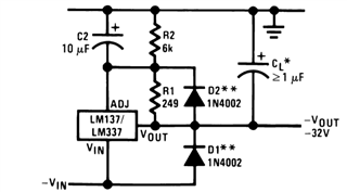
Why capacitor C2 is required?. Is that for ripple rejection?.
What are the criteria for choosing resistor R1?.
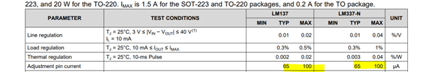
The Maximum value of Iadj is 100uA
How to calculate Iadj?.
If Iadj is current to the adjust pin -1.25/120=10mA of current.