This thread has been locked.

If you have a related question, please click the "Ask a related question" button in the top right corner. The newly created question will be automatically linked to this question.

TPS25982: Applicable Cout(Load capacitor after TPS259827) with our specification

Part Number: TPS25982

Hello,

We have built a PCB using TPS259827 ( referenced thread on E2E : https://e2e.ti.com/support/power-management-group/power-management/f/power-management-forum/834947/tps25982-soa-and-max-cout -> " there is no limit on the amount of Cout. You can increase dv/dt capacitor value to reduce Vout slew-rate (and hence inrush currents) to support large Cout")

From this referenced thread, my understanding was that by adding appropriate C to Cdvdt, large Cout would be applicable.

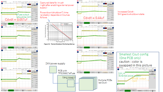
We've built our board using TPS259827 and found that there are critical problem during start-up depends on load (another PCBs) connected after TPS259827.

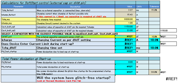
After these evaluation, I've found TPS25982xx_Design_Calculator_RevA.xlsm on TI website.

It seems that it is really difficult(almost impossible) to use large Cout with 24V using TPS259827 due to "Thermal Shutdown Plot During Start-up" (datasheet Figure 53.)

From TPS25982xx_Design_Calculator_RevA.xlsm, it seems that ~1mF is maximum Cout value for Tchg_req 200ms and 2.5mF with Tchg_req 2000ms.

Our system requirement:

  • Vin typ. 24V, Vout 24V
  • Cout ~5mF ( Total capacitance on PCBs connected after TPS259827 )
    • There are multiple bypass capacitors (before circuits) on PCBs connected after TPS259827. Total C amount ~ 5mF
  • 10+ [A] continuous after start-up as normal operation, ILIM 15 [A]
  • Used as 24V switch, part of power-on sequence 

Question :

(1) Are there any kind of solution to solve current issue using TPS259827?

(2) Are there any kind of alternatives?

Best Regards,

Ryo

  • Hi Ryo,

    1. Can you share a waveform showing VIN,VOUT,IN? Are you seeing a failed startup?

    2. Is the load during startup only capacitive or the other downstream circuitry is also drawing current?

    3. One solution is to startup device in current limit. Leave CDVDT open. But for that we have to decrease current limit.

    Regards

    Kunal Goel

  • Hi Kunal,

    1. Sure.

    2. There are multiple input capacitors around ICs. Total amount is about 5mF maximum (ceramic caps and aluminum electrolytic caps)

    These ICs will draw current from those capacitors.

    There are some pull up resistors and diodes, so there might be negligible amount of circuit those draw current.

    3. In case of  CDVDT -> open, slew rate goes faster and inrush current will increase. Is this solution really effective?

    Regards,

    Ryo

  • Hi Ryo,

    1. I see that problem is thermal shutdown because load is large. What is the restriction on charge time? From design calculator I see you have to use a DVDT cap greater than 3.3uF to have startup but charge time will go upto 20s.

    2. CDVDT open helps when current limit is lower than inrush current current because of which inrush current exceeds current limit and device will start in current limit . Also when we leave cdvdt open we do not see delay before VOUT starts rising. But it looks it will not help much in your case because we cannot set current limit to very low value because of application requirement .

    3. Other solution I can think is you add an external resistor+diode from IN to OUT in parallel to efuse. First you charge output cap upto some voltage say 15V through this R+D. Now you can use a comparator to check output voltage . When outptut voltage reaches 15V you send a signal to our efuse enable pin to turn it high and turn efuse one. Now ouptut cap will charge through our efuse and eFuse will see less power dissipation now because voltage difference that it see at output is now 24-15=9v but earlier it was seeing 24-0=24V. Now you can have successful startup at lesser CDVDT cap value.

    Regards

    Kunal Goel

  • Thank you for your reply.

    1. It seems that calculator(rev.A) won't work with large charge time like attached picture.

    Am I using old calculator tool?

    Anyway, too long charge time like  > several seconds is not preferable in our system.

    2. If I could change Cdvdt and Ilim dynamically, it might be manageable. But at this moment, we don't have that kind of structure on our PCB. Will it be feasible (for TPS259827) if I had those kind of control function on my PCB?

    3. Thank you for your advice but that cannot be a solution for us.

    Regards,

    Ryo

  • Hi Ryo,

    1. Yes calculator can not auto calculate cap for large charge time. You need to enter cap value manually . 

    2. We havn't tried dynamic control during startup especially for DVDT . I think it will not work. ILIM you can change after startup to a different value. But problem with this startup in ILIM approach is that  device will start then hit thermal shutdown then restart then hit thermal shutdown. So it will add to charge time. You have to first test this approach on your system with lowest current limit for this device that is 2A. 

    Can you decrease your output cap?

    Regards

    Kunal Goel

  • Hi Ryo,

    Let me know if I can close the thread or there is further query.

    Regards

    Kunal Goel

  • Hi,

    We've done another experiment on this problem but our conclusion is that TPS25982 in not suitable for our application.

    Specification shown on datasheet(on Feature section) of this eFuse was really nice but this eFuse cannot manage heavy C load with in acceptable time scale.

    We will have to re-design our PCB without this eFuse.

    Regards,

    Ryo

  • Hi Ryo,

    I know this is a tradeoff between cout and charge time.  Unfortunately I can not think of other device that can fit in your application. Happy to help you in future with other queries.

    Regards

    Kunal Goel