This thread has been locked.

If you have a related question, please click the "Ask a related question" button in the top right corner. The newly created question will be automatically linked to this question.

TPS61241: TPS61241 5V output failure issue

Part Number: TPS61241

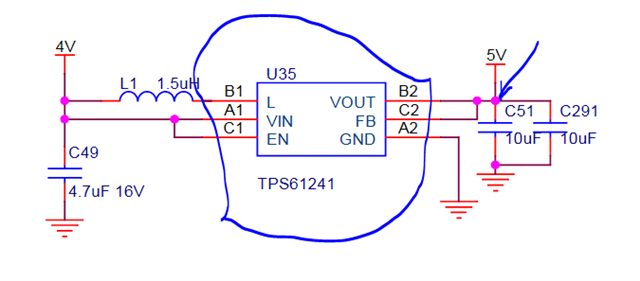
we used the TPS61241 as boost DCDC, the VIN is 3.9V and VOUT is 5.0V, and L is 1.5uH, COUT are 2pcs 10uF/10V X5R, CIN is 4.7uF/16V X7R. And the PCBA is working at high temperature about 85℃ for long time. We building over 100K PCB for user, and now we found about 4-5% PCBA 5V power supply fail. Engineer test 12pcs fail PCBA sample under room temperature and find that 1pcs 5V output is short to GND, 8pcs 5V output is drop to 1.4V, 3pcs 5V output is about 4.2V with a large ripper wave with high temperature. May be the TPS61241 IC fail and how to improve the circuits? 

  • Hi Shupeng,

    Please kindly see my below suggestions for debug: Thanks!

    1.Could you mind doing the ABA swap test and check if the failure goes with IC or failure goes with the board?

    2.Please share the PCB layout for TPS61241;

    3.Could you please also test if it is HSFET failure or LSFET failure on an unpopulated IC?

    (1)HSFET failure: Use the continuity of multimeter and see if HSFET is failed;

    (2)LSFET failure: Use diode mode, anode is at GND and cathode is at L pin; Check if the voltage is ~0.44V;

    -Wenhao

  • 1. Due to the BGA package is very small, the engineer can not success to replace a new IC with the failure board.

    2. Please find the layout as attached.

    3. (1) How to observe the HSFET failure? 

        (2) Can test LSFET on PCBA ?

  • Hi Shupeng,

    1.If we are not able to do a ABA swap. That is ok. We can do some conservative test and check if we could find root cause;

    2.For the PCB, I see you connected FB to VOUT before output capacitor. It is not ok because the trace between VOUT pin and COUT is very noisy and could cause undesirable behavior on VOUT. I strongly recommend you place at least 1 0.22uF or 0.47uF or 1uF caps before 10uF as is to mitigate noise. Also remember to place FB after COUT. Like what shown in datasheet, figure 22;


    3.When device is unpopulated, test:

    (1)HSFET failure: Use the continuity of multimeter and see if HSFET is failed;

    (2)LSFET failure: Use diode mode, anode is at GND and cathode is at L pin; Check if the voltage is ~0.44V;

    I have a confident to say it is a layout issue.

    4.Have you ever tested VOUT waveform? How does it look like in light load and heavy load? Would you mind taking a shot for us? Thanks!

    -Wenhao

  • 3. When device is unpopulated, test:

    (1)HSFET failure: Use the continuity of multimeter and see if HSFET is failed;

    A: Some HSFETs res test by multimeter is less than 10K, good sample is over 200K. 

    (2)LSFET failure: Use diode mode, anode is at GND and cathode is at L pin; Check if the voltage is ~0.44V;

    A: LSFET is ok.

    Now we find some failure is C51 shorted and some failure is the  C25 as below schematic,

  • Hi Shuopeng,

    Thanks for confirmation. What is the voltage rating of C51?

    -Wenhao

  • Hi Shupeng,

    When you were testing device, please make sure the device is unpopulated. The high ripple on VOUT because of unstable loop may cause output capacitor to burn, as most of AC current choose to go C51, the temperature stress of C51 should be highest. 

    -Wenhao