This thread has been locked.

If you have a related question, please click the "Ask a related question" button in the top right corner. The newly created question will be automatically linked to this question.

LM5116: Short circuit unlimited response

Part Number: LM5116

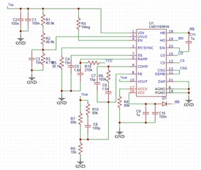
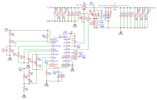
Hello, the full description of my problem is attached in a pdf file. also attached is the schematic of my LM5116 peripherals.

In summary: When stuck in hard short, sometimes while retrying into hiccup mode - the controller will lose current sense and the inductor current will be unlimited.

Please read the pdf for a full description.

Thanks!

4885.LM5116_current_runaway.pdf

  • Hello,

    Per page 15 of the datasheet, the hiccup current limit is designed as a way to internally pull down the system and initiate a new SS cycle if a current limit fault exists for more than 256 cycles. The capacitor connected to the UVLO pin will determine the timing for this hiccup mode.

    On page 27 of the data sheet, a CFT value greater than 1uF is stated to protect the circuit against sustained short circuits and will properly time the UVLO pin. From your schematic, a CFT of 10nF is used. Increasing this value to at least 1uF and modifying the divider network accordingly would help the situation and allow the current limit to properly regulate the system and not leave any residual saturating voltages during the hiccup off times.

    If these issues persist, please provide a full schematic.

    Thank you,

    Joshua Austria

  • Also, please send the power stage schematic and a completed LM5116 quickstart calculator file: https://www.ti.com/tool/LM5116-5116WG-25116DESIGN-CALC

    Regards,

    Tim

  • Thank you Joshua, I didn't notice this demand for CFT, I updated the capacitor to a 2.2uF. This hasn't resolved my issue, although it did lower the chance of the fault occurring, but still at some shorts the current is still unlimited when hiccup is retrying.

    I also noticed something that might be linked to the fault - at the time the response happens the hiccup duty cycle is very unstable, it might indicate that the issue is happening when the short is partial / flickering.

    Timothy - 

    I'm attaching the power stage schematic and the quickstart calculator (although I did not use it to design my converter), Hope this helps.

    Thank you both.
    8244.LM5116_quickstart.xls

  • Hello, the boot cap should be less than the VCC cap - try 0.1uF. Also, tie VCCX to GND directly (not through a 100k resistor).

    I notice from the quickstart that the current limit setpoint is very close to the full-load spec - we normally allow 50% margin here to accommodate nonidealities and load transients (where the inductor current may overshoot, especially with a large Cout). Consider reducing the effective sense resistance value to increase the current limit setpoint. Also, verify there's no noise on the CS signal (an RC filter on the CS lines is sometimes used to mitigate noise).

    Regards,

    Tim

  • By the way, the compensation network values look incorrect based on the quickstart tool recommended values. Target a 10-12kHz loop crossover for a 100kHz switching frequency. Check the stability performance by examining the output voltage behavior during a load transient.

    Regards,

    Tim

  • Thank you for the replies Timothy.

    Unfortunately these have not resolved my issue, I increased the VCC cap, the VCCX to GND was 0Ohm - my schematic was wrong.

    I didn't manage to sense the CS with good enough quality but I did try filtering those inputs with no change. 

    My voltage behavior during load transients was very good and stable. My loop crossover was lower than 10Khz because I had some stability issues during soft start and I fixed them by lowering the bandwidth, my converter is very stable.

    I do not understand why should I increase my current limit setpoint - it is a good design choice but has nothing to do with my fault since I am shorting from no load condition.

    Instead I tried increasing the sense resistor and changing Cramp accordingly, I increased the sense resistor to 10mOhm and this resolved my issue, although of course I'm not getting my desired power output so this is not a valid fix for me.

    The higher sense resistance should increase the signal to noise ratio so maybe my problem has something to do with noise. but my layout is perfect - the sense lines are routed together and do not get close to any noisy lines.

    Thanks.

  • Just looking at the quickstart again, the feedback resistances were entered incorrectly (10 Ohms instead of 10k, etc.) My recommendation is to reduce the compensation and feedback impedances by at least a factor of 2 to make everything less noise susceptible. Check the quickstart file with the resized FB resistors and ensure you have the correct electrolytic cap ESR. Also, the ceramic value is not the full 40uF as some derating occurs with voltage. In addition, you shouldn't need the lead network across the upper feedback resistor. Use a 0.1uF boot cap.

    What are the MOSFET and inductor part numbers? Make sure the 100V FETs are good with a 7.5V gate drive. And check that the inductor is not saturating by probing the inductor current and verifying it stays below its sat current rating.

    Regards,

    Tim