This thread has been locked.

If you have a related question, please click the "Ask a related question" button in the top right corner. The newly created question will be automatically linked to this question.

BQ79616-Q1: Busbar measure flexibility

Part Number: BQ79616-Q1
Other Parts Discussed in Thread: BQ79616

Hello TI Team,

I want to use the BQ79616-Q1 in a distributed BMS architecture: a central unit and multiple CSCs (cell supervisor circuit).

Our target is to produce a single CSC that could be suitable for different battery pack configuration (6s module, 8s module, 12s module).

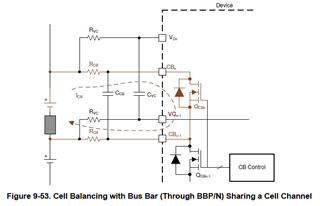
We want the capability to measure the busbars voltage and in that case the plan is to use the relative VC input couple, The busbar could be assigned to any VC couple (depending on battery pack configuration). We know that for VC0-VC1 is not possible, but what about the other input?

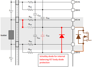
In the datasheet there is written that if you want to measure the busbar with a VC couple you have to disconnect the relative CB input in order to avoid reverse curren flowing into the balancing Mosfet. This statement brokes the flexibility of our design, because in the design the CB inputs are always connected toward the connector.

The plan is to use every input channel (except the first) for cell sensing or busbar sensing, without changing the PCBA

Could we mantain the CB inputs always connected to the connector interface and protect the balancing mosfet with an external shottky diode?

This could improve the robustness in case busbar negative voltage.

Thank you very much

Best regards

Fabio

  • Could you confirm that this configuration could be implemented?

    Thank you very much

  • Hi Fabio,

    Yes everything that you mention above is true and your understanding is correct.

    Just as an idea, have you looked into Figure 9-53 "Cell Balancing with BusBar". I am adding the Figure here for reference:

    I need to check with our design team if the configuration you are proposing could be implemented and I will let you know.

    However in your proposed configuration, the forward voltage on the Schottky diode has to be < 0.3V which might be a bit hard to obtain. Also the measurements will be limited to that voltage (i.e. 0.3V), will this be enough for your application.

    Thanks,

    Viktor.

  • Hi Fabio,

    Another solution to your application might be to identify all Busbar locations for all modules (6s, 8s and 12s) and leave these Cell channels open. If your highers cell solution is 12s the BQ79616 has 16 channels so you can potentially reserve 4 for Busbar.

  • Hello Viktor,

    thank you very much for your support.

    I agree with you regarding the external diode. We have to check with our customer if -0.3V (more or less) could be enough for busbar diagnosis during the charging phase. I will wait the feedback from TI design team on this topic.

    I like your idea to reserve some channel for busbar measure, we have to check in which channels the busbars needs to be measured among the different battery pack configurations and if this does not affect the total CSC number.

    Thank you very much for your proposal. We'll share them with our customer.

    I'll also wait the feedback from TI design team regarding the Schottky diode and then we could close this topic.

  • Hi Fabio,

    I got feedback from the design team that the circuit with Diode is ok however the accuracy might be degraded on the channels that are adjacent to the BusBar channel. This is because of the IR drop across the cable when the BusBar voltage goes negative and significant amount of current starts flowing through the diode/cable.

    Regards,

    Viktor.