This thread has been locked.

If you have a related question, please click the "Ask a related question" button in the top right corner. The newly created question will be automatically linked to this question.

BQ76942: Technical Inquiry on internal regulator(REG1)

Part Number: BQ76942

Hi Guys, 

Good day! We need your help to clarify if customer cannot interface an analog device that can output a maximum of 3.3V with the ADC of BQ76942?

This is related to e2e post before: Query regarding firmware development for BQ76942

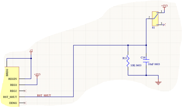
They are integrating a feature to power On/ Off BQ76942 using the RST_shut pin via a SPDT switch (ckt diagram attached). The 3.3V is supplied through the internal regulator (REG1), but once the device enters shutdown mode the REG1 output is disabled.

In section 12.3.2 of datasheet, its mentioned "If pullup resistors for serial communications are connected to the REG1 voltage output, the REG1 voltage can be overdriven from an external voltage supply on the manufacturing line, to allow communications with the device."

Does this mean an external 3.3V can be applied to REG1 pin when REGIN and REG1 are enabled internally in the firmware? This will always supply 3.3V logic high to RST_SHUT pin even when the BQ76942 is completely turned OFF.

And also is it possible to supply this external 3.3V to REG1 pin and disable REGIN so as to not use internal regulator and still assert V(OH) logic of MISO pin to 3.3V?

Finally, we just need clarification. When one of the multifunctional pins are configured as ADCIN, its maximum input is set to 1.8V as per datasheet. So we cannot interface an analog device that can output a maximum of 3.3V with the ADC of BQ76942?

Thank you for your support

Best regards,

Jonathan

  • Hi Jonathan,

    Sorry for the late reply. What the data sheet is saying is that if the device is powered on but the regulators are not enabled and the mcu is powered by the regulators you can, in a production line, include pull up resistors to REG1 and then apply the external voltage to REG1 so it can turn on the mcu. Once the mcu is on, it can communicate to the bq76942 to enable regulators. At this point the regulators will be enabled and you can remove your external voltage source.

     Based on your questions, yes you can technically apply 3.3V to REG1 even if REGIN and REG1 are enabled already, but there would be no reason to do this, plus you will have significant current draw. If the device is in SHUTDOWN mode the whole part is disabled so the regulators would turn off. Then the next time you power the device the registers will be loaded with either the default values or whatever was programmed to OTP.

    In terms of the multifunction pins used for ADCIN, yes the max input voltage is 1.8V and shouldn't be exceeded.

    I hope this helps, but could you maybe describe this application further? I think generally if BQ76942 is in shutdown you are looking to not use the regulators. It is also possible to put the part into DEEPSLEEP mode which turns off the protections but keeps the regulators on if this is the application you are looking for. The current draw is about 9uA in DEEPSLEEP while it is 1uA in SHUTDOWN. You could potentially use an external LDO with low current draw for you mcu instead of the one on the bq76942.

    Best,

    Andrew

  • Hi Andrew,

    Thank you for your response. Here is our customer's feedback.

    "The main constraints of our system are as follows:
    1) In our case, the MCU operates at 3.3V and the BQ76942 communicates via SPI. So as per Section 14.3, the SPI_MISO pin need be programmed to instead use the REG1 LDO for its output drive. So that's why its important to us to configure REG1 to 3.3V.

    2) We are integrating a switch so as to toggle between two modes during charging-
    a) One where it is carried out internally using cell balancing network of BMS
    b) Other where user can disable the BMS and connect the battery to a balance charger.

    For this we are planning to assert or dessert the RST_SHUT pin using a SPDT switch manually. But the problem is if the device enters SHUTDOWN mode, REG1 is disabled and the pad of the switch connected to it will be floating. That's why an external 3.3V is important to always pull the state of the switch's pin high.

    We don't mind supplying 3.3V externally using a DC-DC converter. But I would want both the functions described above to be executed either using the REG1 or external 3.3V. Also I want to put BQ76942 to shutdown/ deepsleep using a switch connected to a pin rather than serially. With this information what are your suggestions?"

    Thank you.

    Best regards,

    Jonathan

  • Hi Jonathan,

    Thank you for communicating to the customer.

    The two modes make sense. However, for the SPDT switch, I don't think it matters if there is a constant 3.3V pulling the switch high. The part does not require the RST_SHUT pin to be held high when in SHUTDOWN mode. Once you hold the RST_SHUT pin high for greater than 1 second it will commence shutdown operations, at which point the device will turn off. The device won't turn on until you meet the wake conditions (the most common being pulling TS2 pin low while in the shutdown mode).

    Deepsleep is an option but there is no physical pin that puts it in this mode only through serial communication or permanent fail occurs. (You could use a multifunction input pin and have a switch here that pulls it high, then have the MCU read the pin value and if it's high then you can communicate the deepsleep subcommand).

    Certainly, though, if you require the MCU to remain on when the bq76942 is in shutdown then you will have to use the external 3.3V supply. 

    Hope this helps, please let me know if there's anything else I can clarify.

    Best,

    Andrew