This thread has been locked.

If you have a related question, please click the "Ask a related question" button in the top right corner. The newly created question will be automatically linked to this question.

UCC21710: How to use OC pin of UCC21710 for Desat protection?

Part Number: UCC21710
Other Parts Discussed in Thread: UCC21750

I am currently designing a gate driver for SIC. I want to make a board where I can use UCC21710 if UCC21750 is not available or vice versa. So as shown in the below picture the Desat circuit is fine for UCC21750, now if UCC 21750 is not available in market and if I have to use UCC21710 then, I want to know how to use the OC pin of UCC21710 for DESAT protection?
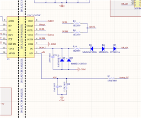
                                      Fig.1

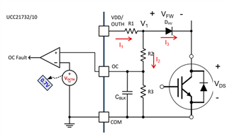
The below figure shows the circuit for using the OC pin for desat protection in UCC21710

                                     Fig.2

Now it is said in the explanation (in Page 41 of UCC21710 datasheet) that the Resistors R1 and R2 should be higher than pull down resistance of internal mosfet, now the questions are as folows

1) how much is the internal mosfet resistance? 

2) How to choose R1, R2 and R3 and R_desat?

3) With the circuit used in the Fig 1. how to design the R1, R2 and R3 and R_desat in order to have the Vds_during short circuit is 4V or less?, I am using a SIC Mosfet NVH4L040N120SC1 (2 in parallel) (used in 3-phase inverter)

4) How Vocth differ from Vdesat (9 V)?

5) how to achieve a 500ns or less blanking time with OC pin?

Thank you

Vijaymahantesh V Surkod

  • Hi Surkod,


    1) The internal Fet has a resistance of ~25 Ohms.

    2) Rdesat determines the current through the HV block diode, and should be chosen to define the forward voltage across the HV block diode. R1, R2, R3 and Cblank are used to set the trigger voltage and blanking time.

    3,5) The UCC217xx models have an excel calculator to help determine the required external component values for the required blanking time (500ns) and detection voltage (4V). It can be found in the UCC21710 product folder, and is also attached to this comment.

    4) VOCTH is the .7V threshold voltage at the OC pin of the UCC21710 for triggering short circuit protection. It is much lower than VDesat on the UCC21750 because it is mainly intended to be used in a shunt measurement configuration.

    Best regards,
    Nicholas DiLauro

    sluc695.zip

  • I have used the tool but it does not include R_desat (using OC pin for Desat protection). That if R_desat is present then how the Voc(det) will be. Please loo at the below picture, do you think the calculations seems fine and If I use a R_desat of 1k and zener of 1.8 v I will be able to achieve a 4V Voc(det) and blanking time of aroun  400ns?

    Thank you

    Vijaymahantesh V Surkod

  • R_desat is only for setting Vfw (forward voltage of the HV block diode). For adjusting the DESAT threshold using a zener diode, please refer to the attached document, Adjusting the DESAT Threshold . Your calculations seem appropriate. 

  • Hi,

    R_desat will limit the current through the diodes and also will change the threshold detection voltage.

    Formula 10 of ucc21710 would be.

    Vdetection = Vth * (R2+ R3)/R3 - n * Vf  - I * R_desat.

    where Vth = 0.7

    n= number of diodes in series.

    Vf = Forward voltage through the diodes.

    I is the current through the diodes.

    How can be computed the current I through the diodes in order to know the real threshold voltage that will be set ?

    Thank you,

    Aitor

  • Hi Aitor,

    Since the OC circuit consists of a resistor divider and a pull-up resistor that will acts the current source from VDD or OUTH R_DESAT is not needed in this circuit. The current through the diodes can be calculated by choosing the VDS threshold you would like to detect the short circuit at and then properly sizing the R1 to get the required Vfw.

    1. Choose the VDS at which you would like to trigger the short circuit detection
    2. Look at the Vfw of you diodes and see how much current is necessary (let's call this current I_3)
    3. With VDS and Vfw find the voltage you would need at node V1(marked below)
      • V1 = Vfw + VDS
    4. With node V1 create the current going into the system (let's call this current I_1)
      • I_1 = (VDD - V1) / R1
    5. Once you have the current you need trough the diode I_3 and current into the circuit I_1 you can solve for I_2
      • I_1 - I_3 = I_2
    6. Once you have I_2 you can properly size resistors R2 and R3
      • R2+R3 = V1 / I_2
    7. After sizing all the resistors you can use the calculator tool to calculate the necessary CBLK to get your desired blanking time tBLK.

    Let me know if there's any questions!

    Best regards,

    Andy Robles

  • Hi Andy.

    now I have understood the operation.

    Thank you.

    Regards,

    Aitor