This thread has been locked.

If you have a related question, please click the "Ask a related question" button in the top right corner. The newly created question will be automatically linked to this question.

BQ24074: CHG pin promble

Part Number: BQ24074
Other Parts Discussed in Thread: BQ28Z610-R1, BQ28Z610, BQSTUDIO

Dear team 

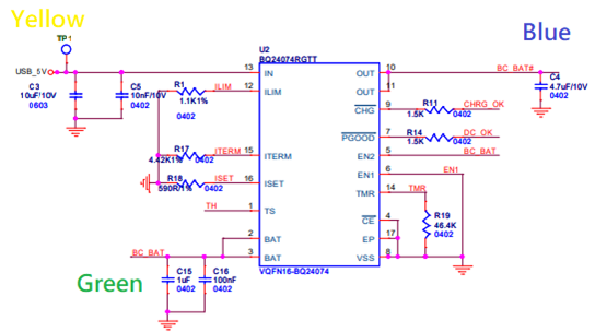
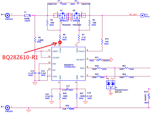
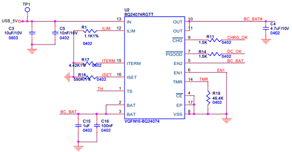
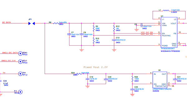
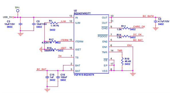
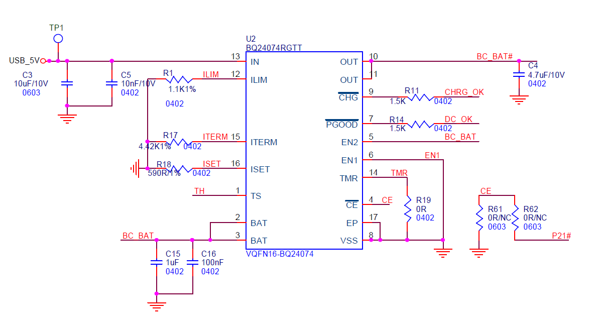
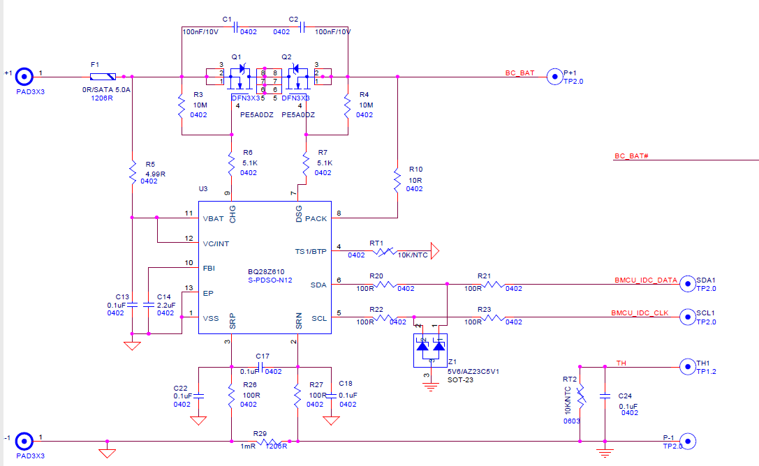
There is currently a battery pack project, both charger and gas gauge use TI part, please refer to the attachment for the complete circuit.

2021-04-21-A7.pdf

Description of the problem:

After the shipping mode (MOSFET on the Gauge side is off), it will wake up after the first USB plug-in, but there is a 25% chance that the CHG light is abnormal.

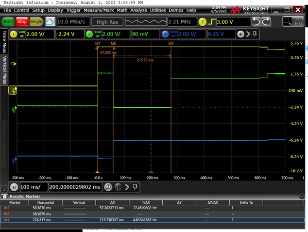
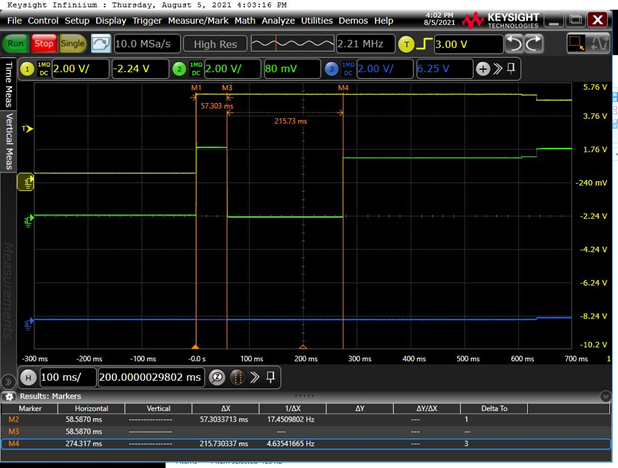
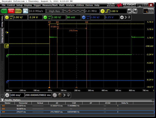
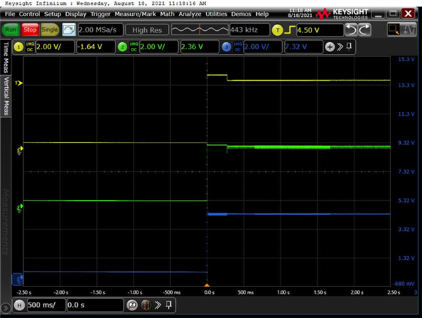
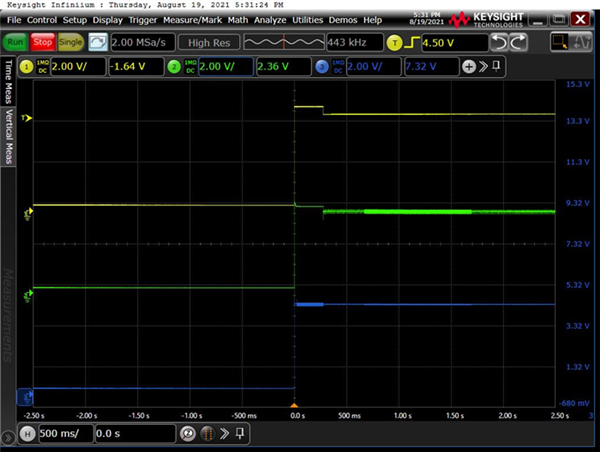
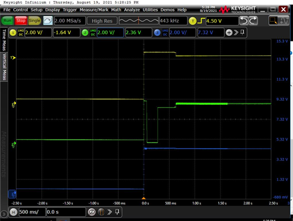
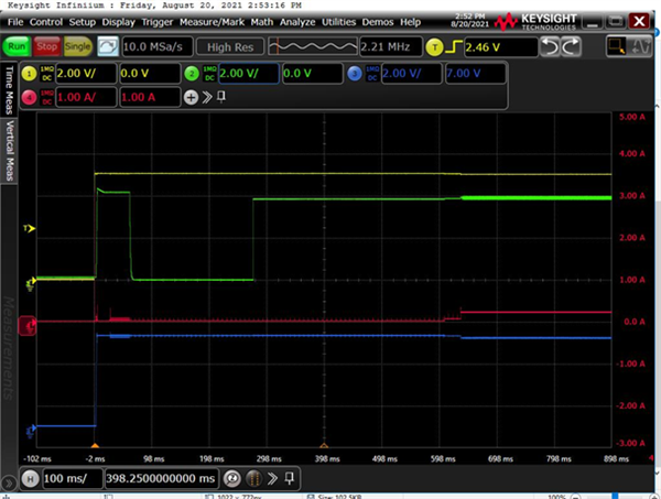
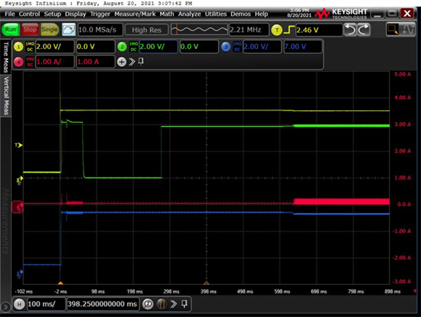
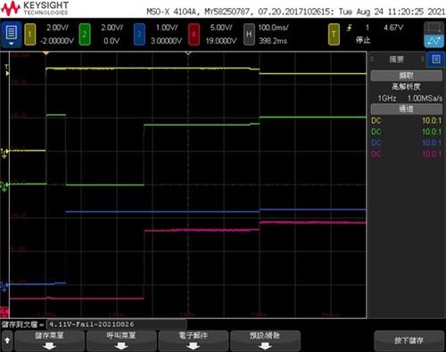
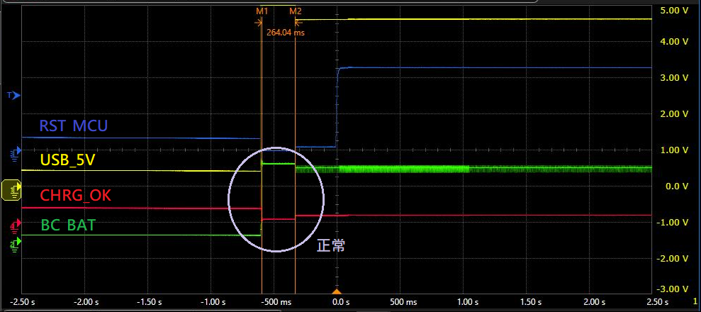
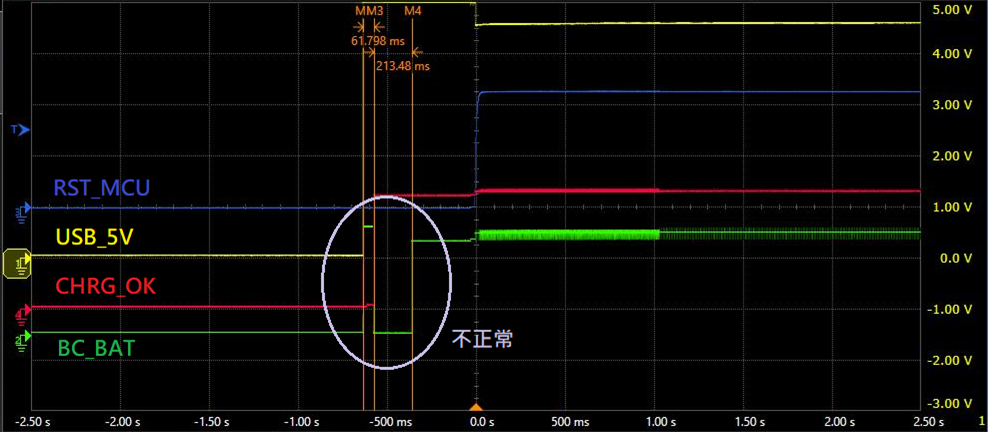
there is a measurement signal for the periphery of the charger, and the following 2 pictures are found, and you can observe the signal of BC_BAT
1. Normal: After USB_5V is powered on, BC_BAT will also be pulled to a high level, and charging will start in about 300msec.


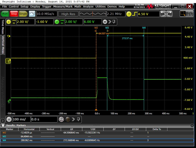
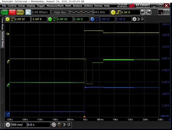
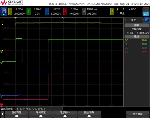
2. Abnormal: After USB_5V is powered on, BC_BAT will also be pulled to a high level, but it will become a low level (0V) when it is maintained for about 60msec.

Could you help to recommend?

Many thanks

Denny

  • Hi Denny,

    To narrow down the issue, is it possible to isolate the battery charger from the gauge? CAn you also verify the connection between the battery and the charger? Outside of the abnormal behavior for 60ms, the noise on the BC_BAT and CHRG_OK signal is more than expected. Is it possible to zoom in on the noise as it is more prominent when the behavior is being seen?

    Best Regards,

    Anthony Pham

  • Hi Anthony

    Thanks for your feedback, the circuitry please refer to the attached file, And I try to cutting the load both charger output(U2_Pin10,11) and BAT output(U2_Ping2,3) Monitor the signal with USB_5V, BC_BAT, CHRG_OK with remove each components.

    6011.2021-04-21-A7.pdf

    After remove all the related parts, the noise looks smaller but the abnormal width still 60msec and drop low, have any comment here?

    BTW, with the TEST3, here only block the loading for charger output(U2_Pin10,11), even get 60msec on BC_BAT but the CHRG_OK keep low here, that means LED will light.

    If you have any comment in advanced please let me know, many thanks!!


    Yellow line : USB_5V

    Green line : BC_BAT

    Blue line :  CHRG_OK

    Test 1:original testing

    Test 2:remove R8

    Test 3:remove R8、R24

    Test 4:remove R8、R24、R10

    Test 5:remove R8、R24、R10、C2、R4、R7

  • Hi Denny,

    Taking a closer look at the schematic, it looks like you don't have the recommended capacitor on the BAT pin. Can you increase the capacitance to the required range (4.7uF to 47uF)?

    Best Regards,

    Anthony Pham

  • Hi Anthony

    Sorry for missing this result, add to capacitance(47uF) on BAT pin, please refer to the below graph.

    The raising/falling time looks a little change but still get abnormal waveform.

    Have any comment of this issue, we still gating on this problem.

    Or need some waveform and other information?

    Many thanks

    Denny

  • HI Denny,

    I've reserved some lab time to look at this more closely tomorrow.

    Best Regards,

    Anthony Pham

  • Hi Denny,

    The 60ms could potentially be a recovery time from a short circuit on the output. Would you be able to provide a waveform of the output as well? Just to be sure, this is with the battery connected directly to the BQ24074 and not to the gauge IC?

    Best Regards,

    Anthony Pham

  • Hi Anthony

    Here you are, if need to check other point please let me know and share some comment for further analysis, thanks!!                       

    Yellow : USB_5V

    GreenBC_BAT (Battery)

    BlueBC_BAT# (OUT)

    1. V780B BC_BAT Normal sample

    2. V780B BC_BAT Abnormal sample

    Many thanks

    Denny

  • Hi Denny,

    Is the BAT capacitor still within range or is it still according to the schematic?

    Is it possible to measure the CURRENT waveform at IN, OUT, and BAT while also showing the BAT voltage waveform? I don't see any issues based on the voltage at the OUT. Is it also possible to check the resistance at ISET and ILIM pins?

    As this isn't typical, the /CHG is high impedance temporarily before shorts are checked for. I'd like to see where exactly in the startup this is occurring. It'd also be great to if you could shift the startup to the left so that the 0s is where the -2s marker is.

    Is it also possible to test this at different battery voltages? I have a suspicion this may be the battery detection routine occurring as it is low for about 250ms which is about how long the battery detection can occur. 

    Thanks for being patient and best regards,

    Anthony Pham

  • Hi Anthony

    The customer's reply as below.

    Is the BAT capacitor still within range or is it still according to the schematic?

    This 2 are new battery pack, so the cap. value is same as schematic , So I will capture the waveform with 10uF today. <= Due to the footprint of 10uF is 0402 and it’s fit on our PCBA, 47uF is only 0603 package…if you have concern please let me know.

    Is it possible to measure the CURRENT waveform at IN, OUT, and BAT while also showing the BAT voltage waveform? I don't see any issues based on the voltage at the OUT. Is it also possible to check the resistance at ISET and ILIM pins?

    I can measure the CURRENT waveform but only one channel, I will check the current probe status later and not problem of showed both current & voltage.

                 Regarding to ISET , ILIM

    Resistor of ISET, recommend range is 590ohm to 8.9Kohm ~ our PCBA used 590 +/- 1%... that I will try the big one 650 ~ 1K ohm resistor and observe the waveform.

    Resistor of ILIM, recommend range is 1.1Kohm to 8Kohm ~ our PCBA used 1.1K +/- 1%... that I will try the big one 1.2K ~ 2K ohm resistor and observe the waveform.

    As this isn't typical, the /CHG is high impedance temporarily before shorts are checked for. I'd like to see where exactly in the startup this is occurring. It'd also be great to if you could shift the startup to the left so that the 0s is where the -2s marker is.

    No problem of our oscilloscope, I can set up for monitor the +/- 2.5sec, but the graph I provide before is already use this setting, if no problem of this setting, I will capture the /CHG waveform to you.

    Is it also possible to test this at different battery voltages? I have a suspicion this may be the battery detection routine occurring as it is low for about 250ms which is about how long the battery detection can occur.

    This one is a little confuse to me, because this problem is happen with shipping mode, this mode means the MOSFET are off state.

    After plug-in, the abnormal waveform is appears before MOSFET turn on and also list below 2 items for reference

    • According the previous testing, even we cut off the loading both OUT , BAT the abnormal waveform still exist.
    • We use only one battery for testing the voltage is around 3.6V, the good PCBA still have normal result but bad PCBA still have this abnormal waveform.

     Thanks for your remind, I will check all the cap. resistors are fit the datasheet range and let you know the value!!


    Update for 1st item, the capacitor change 10uF, thanks!

    1. V780B BC_BAT Pass sample (Change C15_10uF/0402)

    2.V780B BC_BAT Fail sample (Change C15_10uF/0402)

  • Hi Denny, 

    This one is a little confuse to me, because this problem is happen with shipping mode, this mode means the MOSFET are off state.

    Neither the BQ24074 or the BQ28Z610-R1 have ship mode. Are you referring to the system? 

    If the FETS are off on the BQ28Z610 and the BQ24074 is not seeing a battery, this sounds like the battery detection routine. If the test is conducted on the board with abnormal behavior with a lower battery voltage, you may see the the voltage drop to the true battery voltage. 

    No problem of our oscilloscope, I can set up for monitor the +/- 2.5sec, but the graph I provide before is already use this setting, if no problem of this setting, I will capture the /CHG waveform to you.

    I just wanted to see more of the waveform after the device had turned on. This isn't required. 

    I can measure the CURRENT waveform but only one channel, I will check the current probe status later and not problem of showed both current & voltage.

    If you're able to show the current waveforms of each in individual images this is also fine.

    Best Regards,

    Anthony Pham

  • Hi Anthony

    The customer's reply as below.

    Neither the BQ24074 or the BQ28Z610-R1 have ship mode. Are you referring to the system? 

    If the FETS are off on the BQ28Z610 and the BQ24074 is not seeing a battery, this sounds like the battery detection routine. If the test is conducted on the board with abnormal behavior with a lower battery voltage, you may see the the voltage drop to the true battery voltage. 

    The customer feedback:

    The definition of battery pack is let gas gauge turn off the MOSFET, our product will connect to the system(doorbell) if w/o turn off the MOSFET will cause very high standby current.

    You are right, the BQ28Z610&BQ24074 are not seeing a battery … it’s need to plug-in 5V USB to turn on the MOSFET(like you said, detection routine) <= this action called “wakeup from ship mode”

    Normal waveform(Charger_BAT) : with “wakeup from ship mode”, the LED indicator are correct, both Green & Red LED are light.

    Abnormal waveform(Charger_BAT) : with “wakeup from ship mode”, the LED indicator are not correct, only Green LED light <= it’s looks detection routing have some problem

    So, refer to this clue, I want to know why some charger have abnormal waveform, refer to previous DOE, even cut-off all the loading of charger, the waveform still incorrect.

    -------------------------------------------------------------------------------------------------------------------------------------------------------------

    Due to current PCB layout can’t cut for BC_BAT(Pin2,3) measuring, so only set the current probe on IN / Out individually.

    Yellow : IN (USB_5V) voltage

    Green : BAT (BC_BAT) voltage

    Blue : OUT (BC_BAT#) voltage

    Red : current probe

    5V input current(Pin13)

    Charger output (Pin10,11)

    Many thanks

    Denny

  • Hi Denny,

    Based on these waveforms, I believe what the customer is calling abnormal behavior is simply the battery detection routine. This is an automatic process done by the device whenever a battery is not present/connected. 

    The definition of battery pack is let gas gauge turn off the MOSFET
    it’s need to plug-in 5V USB to turn on the MOSFET

    The customer has described the FETs (I assume on the BQ28Z610-R1) to be a factor in connecting the battery to the charger. So let's investigate this further. Can we get a waveform showing the voltage at the following pins:

    • CHG on the BQ28Z610-R1
    • VBAT on the BQ24074
    • VIN on the BQ24074
    • /CHG pin on the BQ24074

    And can we also try with different battery voltages?

    Best Regards,

    Anthony Pham

  • Hi Anthony

    The customer's reply as below.

    No problem of waveform capture, just clarify some setting in details, thanks!!

    1. CHG on the BQ2828Z610-R1 <= please refer to the below partial circuitry, is this the correct location(red circle)?
    2. Regarding to various battery voltage, I propose to 3.6V(30%) & 4V(80%), I will prepare the 2 kinds of battery.
    3. I will take the new one abnormal sample for signal capture, if some parts need to change please let me know.

    Many thanks

    Denny

  • Hi Denny,

    Yes, this should be fine for where to probe for the CHG on the gauge. 

    Best Regards,

    Anthony Pham

  • The customer's reply as below.

    One more clue for your reference, I try to reduce the loading of BC_BAT.

    So I remove C7  and I found the LED behavior become normal.

    But I can not remove all the capacitor and it’s just only one PCBA result. Just for reference, thanks!!

    Many thanks

    Denny

  • Hi Denny,

    The device is taking some time to charge the capacitor from the system and due to the current needed to charge the capacitor, the battery is supplementing the current for some time. You can see in the original image that the 5V source is dropping a bit  from attempting to supply all the current that the device is entering DPPM mode to the point that the battery needs to supplement.

    The ~60ms is the recovery time for supplement mode which is also seen in each of the waveforms. 

    The device is behaving normally and operating in supplement mode. The required capacitance at the OUT pin should be 4.7uF to 47uF. Ensure that this capacitance is as close to the OUT pin and that the path to GND is as short as possible. 

  • Dear team

     The measuring result please refer to the below

     And one more thing want to let you know that I have 5pcs testing with various capacitor of OUT.

    Big capacitor will have /CHG incorrect behavior.

    Less capacitor will become normal.              

    But recommend capacitor range of OUT is 4.7uF ~ 47uF but 47uF will get this problem.

    -------------------------------------------------------------------------------------------------------------------------------------

    Yellow : VIN (USB_5V) voltage

    Green : BAT (BC_BAT) voltage

    Blue : /CHG pin on the BQ24074 voltage

    Red : CHG on the BQ28Z610-R1

    Battery 3.65V

    Battery 4.11V

    Many thanks 

    Denny

  • Hi Denny,

    Thanks for the waveforms.

    It does in fact look like the device is running the battery detection routine prior to the BQ28Z610-R1 pulling its CHG pin high. Once it pulls the CHG pin high, then the FETs connected to it are connected and the BQ24074 is able to see the battery. 

    Would you be able to connect the BQ28Z610-R1 to BQStudio and gather a log during the startup process? This log should show whether the FETs are closed or not.

    Big capacitor will have /CHG incorrect behavior.

    Less capacitor will become normal.              

    But recommend capacitor range of OUT is 4.7uF ~ 47uF but 47uF will get this problem.

    Less capacitance is fine as battery specs will vary. 

  • Hi Anthony

    The customer's reply as below.

    Thanks for your comment, one problem here, what’s the BQStudio and how to use it to gather the log?

    Anthony said : “connect the BQ28Z610-R1 to BQStudio and gather a log during the startup process”

    Many thanks

    Denny

  • Hi Denny,

    BQStudio is the Battery Management Studio software that works with our I2C devices. It connects through the EV2400 

    Best Regards,

    Anthony Pham