This thread has been locked.

If you have a related question, please click the "Ask a related question" button in the top right corner. The newly created question will be automatically linked to this question.

LM5116: Short circuit problem when synchronized to external clock

Part Number: LM5116

Hi,

I have a LM5116 controlled buck converter that is having  a few issues during short circuit. It is used in a multi-output converter so is synchronized to an external clock via the RT pin.

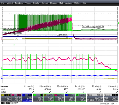
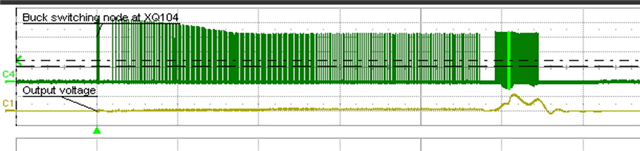
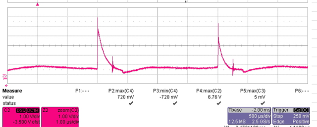
During overload or short circuit switching stops as expected after 256 cycles, then about 100µs later the High-side driver kicks back into life causing the output to rise again as shown below:

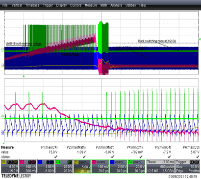
If the external clock is disconnected and the LM5116 allowed to free run the short circuit behaves as it should, initiating a proper hiccup cycle after 256 cycles. For reference I'm using a 10µF ceramic as my UVLO capacitor.

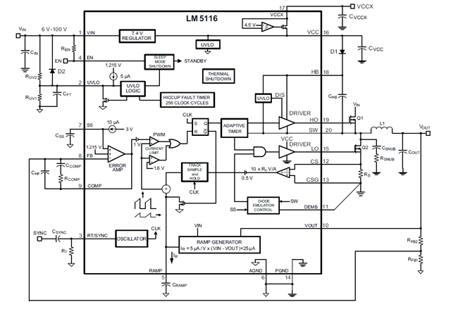
Looking at the block diagram I cannot see any obvious reason why the behavior would be different.

There is a little overdrive above the recommended 5V, but the sync signal appears to be within the limits allowed by the datasheet:

Any ideas as to what might be upsetting the chip?

(NB. Vout, HO, LO and SW are all clamped heavily at the chip's inputs to prevent negative over-voltages)

Quinn Kneller

  • Hi Quinn 

    I will get back to you asap after some bench tests.

    - Eric Lee (Applications Engineer) 

  • Hi Quinn 

    Meanwhile, would you please confirm that your VOUT is not shorted to ground perfectly during the VOUT-short--to-ground test ? Theoretically, the VOUT cannot rise  if the VOUT is grounded.

    -Eric Lee (Applications Engineer)

  • Hi Eric,

    Thank you for replying. You are right that short circuit is not perfect. Most of the testing has been carried out using a contactor to short the output, (when we don't mind blowing the unit up) or a heavy overload of 200% nominal load (when we don't want to have to rebuild the unit). Even a contactor on short leads does not  present zero impedance - when the short is first applied the lead inductance rings with capacitance in the circuit swinging Vout below ground. This really upsets the chip so we have clamped pin 10 with a Schottky and series resistor (pin 10 was directly connected to Vout). The plots I shared were taken with the heavy overload.

    Our main concern is that the uncontrolled High Side switching in this condition could saturate the choke if a short is applied. Also the Low side does not appear to switch during this period, and as far as we can tell from the block diagrams the circulating current is only sampled when the low side switch is on?

    Quinn

  • Hi Quinn 

    I cannot duplicate the behavior which you mentioned on the bench, but  I think it is most likely because the SS capacitor is not fully discharged after the 256 cycles of current limiting. If a noise is injected (by the external synchronization clock) to either UVLO or AGND, the device may restart immediately after the 256 cycles of current limiting without pulling down SS. Please compare SS with/without the external clock.     

    - Eric Lee (Applications Engineer)

  • Hi Eric,

    Thank you for your reply

    Without synchronization it looks like this:

    (green = SW, red = SS)

    With synchronization it does this:

    Quinn Kneller

  • Hi Quinn.

    The datasheet says in the UVLO section that at higher switching frequency (greater than approximately 250 kHz) the hiccup timer may be disabled if the fault capacitor is not used. Based on this description,  I think the external clock signal is coupled to inside the device (especially at UVLO pin)

    Eric Lee (Applications Engineer) 

  • Hi Eric,

    Thank you for reply. I have the fault capacitor fitted, but would be interested to understand how the presence or not of this capacitor affects the hiccup timer. Does this place an effective upper limit on Fsw when synchronized to an external clock, and if so what is the tolerance on that 250kHz? How does this help find a solution to the problem?

    Another thought I had was that the chip has Vccx present throughout this operation. It is a 24V output so we can't easily derive Vccx from the output, and based on the supply current stated in the datebook I don't think tying Vccx to ground and using the internal regulator is feasible either (though I might try that as a test). I was wondering if it was linked somehow to this discussion:

    https://e2e.ti.com/support/power-management-group/power-management/f/power-management-forum/862576/lm5116-spurious-gate-pulses-during-start-up

    In parallel I have an engineer looking at reproducing the issue on your evaluation board. I will let you know how he gets on.

    Quinn Kneller

  • Hi Quinn

    As suggested by Foong. I will close this thread and continue the discussion via email. I will get back to you via email shortly.

    - Eric Lee (Applications Engineering)