This thread has been locked.
If you have a related question, please click the "Ask a related question" button in the top right corner. The newly created question will be automatically linked to this question.
Hi Sir,
When I use the differential remote sense function, can I use 8 mil power trace/8mil gnd trace and the differential length how many mils limitation ?
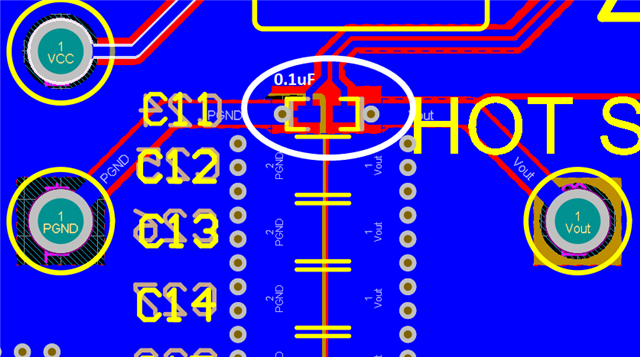
Is the kelvin sensing to put 0.1uF capacitance between power trace and gnd trace near TPS548A29 ?
If I don't want to use differential remote sense, can I use which value of Rfb_hs from FB to VSNS- and add 0.1uF from FB to VSNS- ?
Hi Kevin,
1. As mentioned in the datasheet, " The connections from the FB voltage divider resistors to the remote location should be a pair of PCB traces with at least 12-mil trace width".
2. It should be put near the sensing point. Below is a capture of EVM.
3. If not using remote sense, you can use 10kohm RFB_LS as the resistor between FB and VSNS- and you can calculate the corresponding RFB_HS according to your required output voltage. I recommend not to add any capacitor between FB and VSNS- parallel with the RFB_LS, that would inject a pole in the loop. In most of the cases, that would cause worse load transient performance and less phase margin.
Besides, we have calculator tool and Webench tool on Ti.com: https://www.ti.com/product/TPS548A29. Calculator tool is in "Design tools & simulation". You can use them to help with your design.
Thanks,
Andrew