


Other Parts Discussed in Thread: LM5176
Hi,
We have been developed battery charger using LM5175. We are currently encountering a problem with a high side MOSFET (boost leg) getting very hot; particularly, when we have a battery connect on the output of charger before it was powered up.
I find a below post on the TI forum addressing exactly what we have been dealing with at the moment.
According to this post, there are 2 solutions to solve this issue:
1/ Add extra Schottky diode in parallel with high side MOSFET (boost leg).
2/ Or use LM5176 IC.
We cannot sourcing LM5176 else where at the moment so we cannot really use this option. In regard to option #1, we are still not quite satisfy with a result as the Schottky diode still getting quite hot at full load (20A). The IC operates in diode emulation mode (DEM).
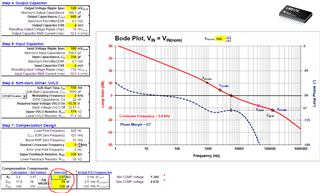
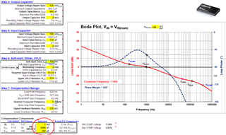
To tackle this issue, we have been playing around with a compensation RC circuit. And we find out that reducing cross-over freq prevents diode from getting hot and IC from operating in diode emulation mode (DEM).
However, it flags another concern that will it cause any "side effects"?, e.g. instability, unit faulty in long-term, etc.
Please see the bode plot below when using a compensation RC circuit as TI's suggestion and our experimental compensation RC circuit.
Last but not least, do you have any guideline to select compensator poles and zero?
What is the relationship between those parameter and cross-over freq?
Any advice would be appreciated.
Thanks,
VT
