This thread has been locked.

If you have a related question, please click the "Ask a related question" button in the top right corner. The newly created question will be automatically linked to this question.

LM3405A: Not getting the expected efficiency

Part Number: LM3405A
Other Parts Discussed in Thread: TPS92200, LM3405

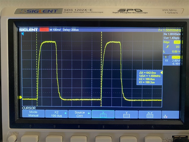
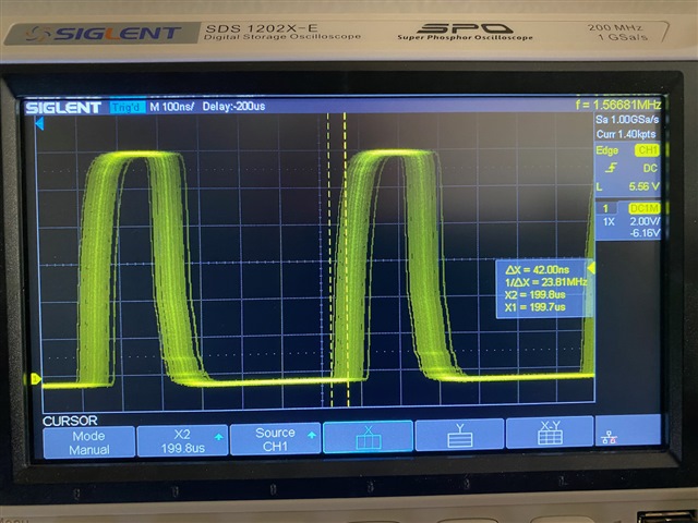
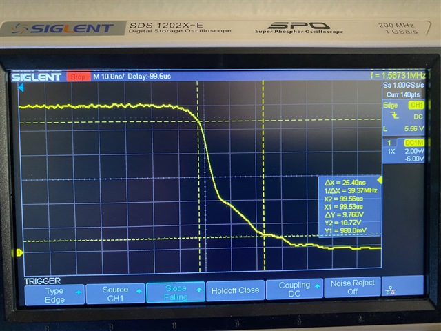
I'm using the LM3405A to drive a single color LED (Vf=2.5, 3.1, or 3.3v) at Iout = 0.7 - 1.0A, with Vin=12v. Based on initial testing, I'm only achieving about 70% efficiency rather than the ~80% efficiency indicated by the data sheet Figs. 1 - 3. I suspect this is caused by high switching losses (Psw) due to slow rise and fall times measured at the SW pin (Trise, Tfall). I measure Trise = 33ns and Tfall = 28ns, considerably higher than the values shown in Table 2. What could be causing this?

I'm currently using an external source (Vext = 5v) to generate Vboost, but in the final design I plan to use the alternative method in Table 14 (Zener diode in shunt configuration). Here are some of there relevant component specs:

Boost capacitor C3: 0.01µF MLCC, 25v, X7R, 10%, 0603 package.

Boost diode D2: Schottky diode, Vf=0.35v, 30v, 100mA, 0603 pkg

Inductor: 6.8µH, 1.6A, DCR=90mΩ, 4.0 x 4.0mm

Catch diode D1: Schottky, Vf=0.44v, 30v, 2A

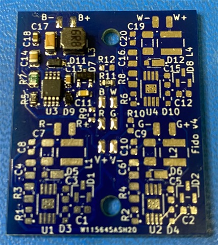
I followed the PCB layout recommendations as closely as possible. 

It just occurred to me that a contributor could be the relatively high DC resistance of the inductor (90mΩ) compared to the physically-larger inductors listed in the BOM (Table 3) and used in the LM3405A Demo Board. I hadn't focused on this because it seems like the LM3405A chip was getting much hotter than the inductor. I'm seeing a chip surface delta-T of 25C with no heat sink or airflow with Iout=0.7A. 

Thanks!

  • Hi since this period is during Chinese mid-autumn festival, out expert will reply you after this Wed. 

  • Hi,

    If you care efficiency so much, how about TPS92200? This is a sync buck LED driver, which brings higher efficiency comparing to LM3405A. In addition, it doesn't need external Zener diode.

    Robin

  • Thanks for your response, but this doesn't resolve my issue:

    1. I selected the LM3405A based on both performance and current availability

    2. I've already invested significant effort in developing a PCB based on the LM3405A

    3. The TPS92200 is not currently available from major US distributors (Digikey, Mouser)

    4. It would be acceptable to achieve the specified efficiency of the LM3405A, even if it's not as good as the TPS92200. 

  • Hi,

    Could you describe your efficiency measurement method including voltage and current meter are placed and a picture is preferred. I assume the lower efficiency is caused by measurement.

    Robin

  • Hi,

    I'm on vacation right now, but will provide measurement data/pictures when I return next week. For now I can say that my measurements are fairly consistent with the power dissipation predictions based on the equations in Section 8.1.8 of the data sheet. In particular, if I were able to achieve Trise = 18ns and Tfall- 12ns as shown in Table 2, the efficiency would be 82% at Iout = 0.67A, per the attached spreadsheet. But with my actual values of Trise = 33ns and Fall = 28ns (10-90% levels), the predicted efficiency is 76%. My measurements suggest it may be worse than this, but I'll get more accurate data next week. 

    The chip/circuit gets pretty hot compared to an off-the-shelf driver board (based on the AL8805W5) under the same operating parameters. 

    Thanks,

    KeithLM3405 Part Values.xlsx

  • Hi, I'm back now. While I was gone I received a new current probe, and today I measured the LED current at 0.68A vs.my previous measurement of 0.67A. But I also measured the LED Vf and see that it's much higher than the nominal value in the data sheet (Cree XML-RGBW). For example the green LED measured Vf=3.42V. That means the delivered power is 0.68*3.42 = 2.33W. The power delivered to the driver circuit is 0.24A * 12V = 2.88W. so the efficiency is 2.33/2.88 = 81%. That's more consistent with the data sheet. The Red LED Vf=2.74V, and the efficiency with that LED is 74%.

    I'm still troubled by the slow rise/fall times I'm seeing on the SW pin. I re-did my measurements, which are consistent with what I said previously:

    Trise = 34ns, Tfall = 25ns (see attached photos)

    The PWM signal at the SW pin has the expected frequency and duty cycle, but there is about 40ns of jitter (see photos). Don't know if that's significant or not. 

    It seems like I could get much better efficiency if the rise/fall times were more in line with the much smaller values mentioned in the data sheet. Any ideas?

    Thanks,

    Keith

  • 10.1 -10.7 is Chinese notional holiday, our expert will reply you after 10.8. if it's an urgent case, please directly communicate with the person who is assigned.

  • hi,

    there shouldn't be jitter on SW node. Can this phenomenon be repeated successfully?

    Robin 

  • Hi,

    The jitter is continuous. I was only able to get a clean trace by using single-shot triggering on the scope. 

    I'll make the same measurement on another copy of the same circuit and report back within 1-2 days. 

    -Keith

  • My measurements were identical on the second board. Continuous jitter of ~40ns with slow rise/fall times.

    -Keith

  • hi,

    it seems loop is a little unstable. please increase the output capacitor value and I think it should be helpful.

    robin

  • For the output capacitor (C2) I'm currently using a 1µF X7R MLCC in a 1206 package. I'll stack two of them to see if 2µF results in an improvement. But do you think this would have an impact on my core issue (excess power dissipation) and the slow rise/fall times I've noted?

    Thanks,

    Keith

  • I tried the following configurations, but none of them had any noticeable impact of the waveform at the SW pin (jitter, slow rise/fall):

    1. Increasing the output capacitor (C2) from 1µF to 2µF

    2. Removing C2

    3. Also removing the feed-forward capacitor (C4)

    -Keith

  • hi,

    i got it and I'll test it on the bench.

    robin

  • Robin,

    Any progress?

    Thanks,

    Keith

  • I just received and tested the new version of my board, which uses the zener diode method to generate Vboost (see attached snippet from schematic). The overall performance is about the same, but the jitter on the SW pin is now gone. I don't know if that's due to the minor circuit change or a slightly different layout. The efficiency is about 78-81% (depending on LED color), and it seems like that's the best I'll get with this device. 

    I'll continue using this part for now, but I'd like to try the TPS92200 if/when if ever comes back into stock (any idea when?). 

    -Keith

    -Keith

  • Hi Keith,

    I think TPS92200 is not available within this year...So at present, LM3405 is a most appropriate candidate.

    BR,

    Robin