Other Parts Discussed in Thread: ISO5852S
Hello Andy,
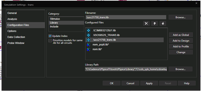
We got the TINA model from below E2E thread.
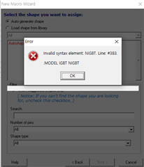
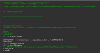
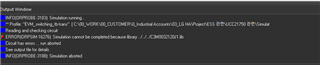
Above model operated well but my customer modified and added FET then the customer got a below error massage.
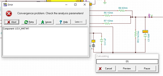
What is the meaning of error massage "Component: U3.X_M47.M1"?
I added the customer TSC file. please review it and let me know your opinion.
Thank you.