This thread has been locked.

If you have a related question, please click the "Ask a related question" button in the top right corner. The newly created question will be automatically linked to this question.

LM5000: output of the boost converter follows the input instead of amplifying it

Part Number: LM5000

Hi everyone!

I'm designing a boost converter with the LM5000, but I'm facing some troubleshootings. 

Firts, some informations about the circuit:

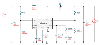
- I designed the circuit using WEBENCH;

- The input varies between 18V and 30V (hardly reaches 30V);

- The output must be 30V (or a max of 32V).

I'm testing the circuit using a PCB. However, the circuit do not works as intended. The output follows the input instead of stay in 30V. For example, if the input is 20V, the output is 20V instead of 30V.

I've already changed the components and tested them on other PCBs.

Any help will be welcome.

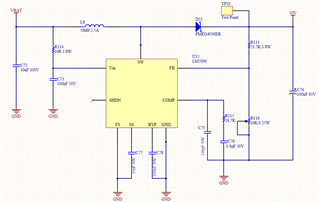
Below, the circuit designed. Note that are some diferences between the circuit designed with WEBENCH and the circuit that was actually implemented. This occurs due to availability of components.

  • Hi Marco,

    Thank you for using the LM5000.  It seems your circuit is not switching, which can be a results of FB staying high.  Please check your R116 setting resistance which should be at 1.02k in order to regulate the output voltage at the targeted level.

    Thanks,

    Youhao Xi, Applications Engineering

  • Hi Youhao Xi, thanks for your reply.

    This was my first thought too. However, I replaced the trimpot for a 1k resistor and the output kept following the input.

    Even before replacing the trimpot, I adjusted it so that the FB voltage stayed in 1.259V (according to datasheet). Even so, I didn't get the expected result.

    Thanks, 

    Marco Beteto

  • Hi Marco,

    Could you measure the following signals in the same scope picture?

    • Vin, FB, COMP and SS
    • BYP, SW, and Vout 

    Best Regards,

    Youhao

  • Hi Youhao,

    Thanks for your reply.

    During the measurement process, I decided to check the components once again. At first, everything was normal, but I found something strange about the diode. I took it off the PCB and tested it, veryfying that it was in short-circuit.

    I replaced the diode with a new one, but the circuit doesn't worked as intended. I tested this new diode and it was in short-circuit too. In this way, I tested all the new diodes that I had bought, verifying that several of them were faulty. I think I was unlucky with the batch of diodes. Hovewer, I found some diodes workig fine and replaced (again) the diode. The circuit is now working fine, with the output voltage being the desired voltage.

    Thanks for all your help.

    Best regards,

    Marco Beteto

  • Hi Marco,

    Congratulations for having found the diode problem.  I think this thread can be closed, right?  You are welcome to add a new post to re-open it, or start a new thread, when you have further questions. 

    Good luck!

    Youhao