


Hi,
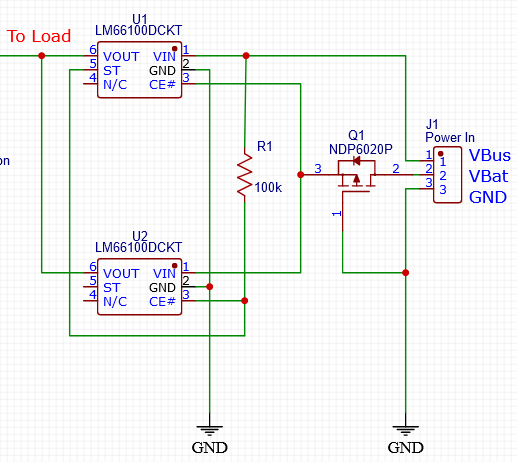
I'm planning to use the circuit, below, utilising two LM66100 to swap power sources from a 3.7v battery source (marked VBat) to a 5v USB source (marked Vbus).
The aim is to power the load from the VBat source until the VBus power source is connected, which then takes over powering the load (also charges the battery separately via a different circuit not shown below). I'm trying to determine the best way to wire up the CE# pins between the two LM66100's so that it minimises the drain on battery (such as parastic pull up/down resistor loads) when the VBus source is not present.
My query is whether it is possible to wire the CE# of the USB LM66100 (U1) to the VBat power in, and CE# of the Battery LM66100 (U2) to the ST output of U1, with a pull up resistor to the VBus line.
Does this approach give priorty to the VBus power source over the VBat power source when both are connected?
Does this approach result in an invalid initial state with the battery only connected, where CE# on U2 is floating?
I've also incorporated a P-Mosfet for reverse current protection back into the battery, as I assume I cannot configure the LM66100 for both RCP and power switching in this particular design.
Many thanks

