This thread has been locked.

If you have a related question, please click the "Ask a related question" button in the top right corner. The newly created question will be automatically linked to this question.

LM7481-Q1: Help with the design to comply with 7637-2 and 16750-2 for a 12V system

Part Number: LM7481-Q1
Other Parts Discussed in Thread: LM7480, LM7481, , LM7480-Q1

Good Morning,

I am working on a sensor project that runs on a 12V system and uses a maximum of 200mA. The space is very tight and I have to go to a minimum number of components possible to comply with 7637-2 and 16750-2 (unsuppressed). I have studied the older and newer revisions of the datasheet and manual for the evaluation board and I am somehow confused. I need to keep the Vout between 6 to16V and turn the Vout off if it goes outside the range. The system however should withstand all DC and transient loads specified in the abovementioned standards. Considering I do not need a very high continuous current and Vout is always below 16V, would you recommend the schematic I can start from?

I have a few questions to ask:

1- For Undervoltage protection, should I use a resistor ladder on EN/UVLO pin just like OV? is the top connected to Vout or Vsens? I don't need to use EN function. It's always on.

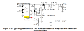
2- Considering it's a 12V system, should I go with a common drain design (Fig 10.1) or a common source (Fig 10.25)?

3- which tests on 7637-2 and 16750-2 will the design in Fig 10.1 fail? it is not mentioned in Table 10.1 if it complies?

4-is there any spice model that I can use for simulations?

5- if  Vout is going to be always below 16V, can drop the voltage rating of C_load to save some room?

6- what is the purpose of D2 in Fig 10.25 and why is OV ladder connected to a mechanical switch (or did I misunderstand the part?)

7- Can I use LM7480 and LM7481 interchangeably in this design?

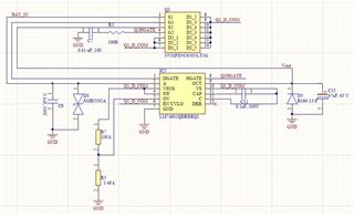
I have attached a quick sketch I have done so far. C_load is the largest component and I haven't done the math for OV ladder to keep it below 16V. Would you mind to review and comment?

Thank you very much in advance.

Hamed

  • Hi Hamed,

    Thanks for your interest on LM7481-Q1. We will get back to you on Monday. 

  • Hi Hamed,

    Since customer wants the circuit to withstand unsuppressed load dump, we recommend using Common Source configuration as shown below. As customer want over voltage cut-off (power path off during over voltage). they need to connect the OV resistor ladder to Vin.

    Please see my response to your other questions below,

    1. If EN/UVLO functionality is not required, you can connect this pin to Vin directly.
    2. Common Source configuration is required if input surge voltages are > the Abs Max rating of the device (70V).
    3. Fig 10-1 represents common drain configuration. This configuration will support suppressed input load dump but will fail unsuppressed input load dump. 
    4. You can find it here. Download here.
    5. When Configured in OV cut-off the output voltage will not go above 16V. It would be customer's call on how much margin they would like to have on output cap voltage rating. I would recommend at least 30% margin.
    6. The purpose of D2 is to supply voltage to the VS pin from A pin. The 10 kohms in series with VS pin (which is placed to limit the current into Zener) limits the current required by the charge pump during startup conditions. So, a diode from A to VS provides uninterrupted current into the VS pin.  Regarding the switch between the OV resistor ladder and input/output, this is to indicate two functionalities - OV cut OFF and OV Clamp. Customer can choose one of the connection based on their requirement. 
    7. Yes, you can use both LM7480-Q1 and LM7481-Q1 interchangeably. 

  • Hi Avishek,

    Thanks for the detailed response. I will get back to you once I moved forward with this.

  • Hi Hamed,

    Sure. You can reach out to us if you have any further questions. 

    Meanwhile, I will close this thread.